Install and Connect MCC1 (Multicarrier) Cabinet
Connect Fiber Optic Interconnect Cabling
SI Installation and Upgrades
357
June 2004
6
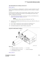
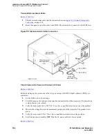
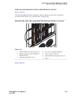
Route the cables from the FROM cabinet down into the cable trays of each EPN cabinet. Connect
the cables to the lightwave transceiver just installed on the TO cabinet.
7
Connect the fiber that comes from the TX connector of the FROM transceiver to the RX
connector of the TO transceiver and vice versa.
8
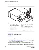
Route the cables through the cabinet and through cable organizers as provided. Secure the cables
to the cable-tie rack.
Return to Task List
Connect Standard-Reliability CSS-Connected System with 1 Switch Node
Return to Task List
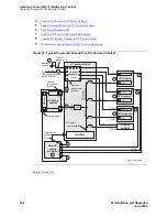
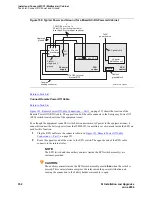
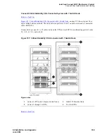
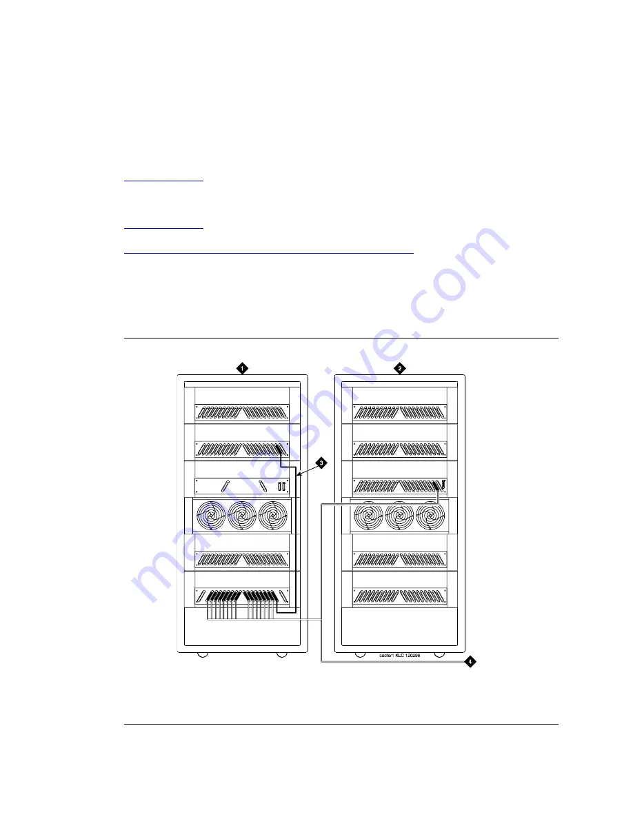
Figure 105, Standard Reliability CSS-Connected with 1 Switch Node,
on page 357 shows typical fiber
optic cabling between cabinets. The cable between the EI and SNI on the PPN is a pre-installed metallic
cable (H600-278).
1
If no running list is available, use the outer slots first in alternating order. Connect the first 2 SNI
slots to 3 and 20 (the leftmost and rightmost of the unused slots). Next, use 4 and 19, and so forth.
2
Add links to the EPNs in alternating order (20, 3, 19, 4, 18, 5, and so forth).
Figure 105: Standard Reliability CSS-Connected with 1 Switch Node
Figure notes
1
Cabinet 1 (PPN with 1 Switch Node)
2
Cabinet 2 through 16 (EPN)
3
H600-278 Metallic Cable
4
To other EPNs


