background image

Bring the System Online
Task List: Administer the System

466

SI Installation and Upgrades

June 2004

2

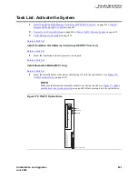
If the system has IP endpoints registered, unplug the Ethernet cable from the TN799 (C-LAN) 
circuit pack.

This disconnects (unregisters) all IP endpoints.

3

Type 

set time

 and press Enter.

Ensure that the system date and time are set correctly.

4

For duplicated systems only type 

status system all

 and press Enter.

Ensure that the standby SPE is not in the maintenance state. If it is, wait for the maintenance state 
to finish.

5

Use one of these installation methods:

Direct connection between the switch and RFA

No connection between the switch and RFA

Direct connection between the switch and RFA

a

Go to the RFA website, and, following the instructions in the “Deliver to G3r/G3si/G3csi” 
chapter of the RFA Job Aid, deliver the License File.

NOTE:

This procedure sends the License File to the switch and installs it.

b

If the system has IP endpoints registered, and you unplugged the Ethernet cable from the 
TN799 (C-LAN) circuit pack, replug the cable.

This re-registers the IP endpoints.

No connection between the switch and RFA

a

Go to the RFA website, and, following the instructions in the “Deliver to G3r/G3si/G3csi” 
chapter of the RFA Job Aid, deliver the License File to your laptop/PC.

b

Open the License Installation Tool (LIT) application at your laptop/PC.

c

Use the LIT instructions to add a switch connection profile to the tool.

d

Use the LIT instructions to install the License File on the switch.

e

If the system has IP endpoints registered, and you unplugged the Ethernet cable from the 
TN799 (C-LAN) circuit pack, replug the cable.

This re-registers the IP endpoints.

Return to Task List

Summary of Contents for MCC1

Page 1: ...Avaya MCC1 SCC1 Media Gateways Installation and Avaya DEFINITY Server SI Upgrades Made Easy 03 300189 Issue 1 June 2004 ...

Page 2: ...sions may be either to through synchronous time multiplexed and or circuit based or asynchronous character message or packet based equipment or interfaces for reasons of Utilization of capabilities special to the accessed equipment Theft such as of intellectual property financial assets or toll facility access Eavesdropping privacy invasions to humans Mischief troubling but apparently innocuous ta...

Page 3: ...l aggregators to block access dialing codes is a violation of the Telephone Operator Consumers Act of 1990 REN Number For MCC1 SCC1 CMC1 G600 and G650 Media Gateways This equipment complies with Part 68 of the FCC rules On either the rear or inside the front cover of this equipment is a label that contains among other information the FCC registration number and ringer equivalence number REN for th...

Page 4: ...ons may not prevent degradation of service in some situations Repairs to certified equipment should be coordinated by a representative designated by the supplier Any repairs or alterations made by the user to this equipment or equipment malfunctions may give the telecommunications company cause to request the user to disconnect the equipment Declarations of Conformity United States FCC Part 68 Sup...

Page 5: ...ger 2 1 39 Read this first 39 License File 39 Service interruption 39 Call Management System CMS 39 Software compatibility 40 Usable circuit packs 40 Wireless systems 40 Antistatic protection 40 Task list R9si 10si Communication Manager 1 x to Communication Manager 2 1 40 Pre upgrade checklist 42 Go to the RFA website 43 G3V4 through Release 9si upgrades only 43 Direct connection between the switc...

Page 6: ...ion between the switch and RFA 53 No connection between the switch and RFA 53 Administer no license emergency numbers 54 Set Daylight Savings rule 54 Verify the upgrade 55 Check link status 55 Verify software version 56 Standard Reliability 56 High or Critical Reliability 56 All 56 Power up DEFINITY LAN Gateway system 56 Power up DEFINITY AUDIX system 56 If the AUDIX was removed from the cabinet 5...

Page 7: ... 74 Check existing software load from G3V4 75 Verify system status from G3V4 75 Disable scheduled maintenance and alarm origination from G3V4 76 Record all links and remove only ISDN interface links from G3V4 76 Save translation from G3V4 77 Save translation duplicated system from G3V4 78 Save announcements TN750 or TN750B only from G3V4 78 Shut down DEFINITY LAN Gateway from G3V4 79 Shut down DEF...

Page 8: ...translation TN750 or TN750B only from G3V4 92 Return equipment from G3V4 93 Helpful links 93 R5 R6 R7 R8si to Avaya Communication Manager 95 Introduction 95 When to use the TN2401 versus the TN2401 2400 sandwich pack 95 About circuit pack carriers 97 Before you begin the upgrade 97 Preparation and process steps 97 Make the Blowback Tape 100 Task List R5 R6 R7 R8si to Avaya Communication Manager 10...

Page 9: ...19 Replace TN772 duplication interfaces with the TN792 duplication interfaces R6si or earlier from R5 R6 R7 R8si 119 Install TN2404 and TN2401 circuit packs and original translation card s from R5 R6 R7 R8si 120 Power up the system from R5 R6 R7 R8si 121 Set Daylight Savings Rule from R5 R6 R7 R8si 122 Deliver or install the License File from R5 R6 R7 R8si 122 New Duplicated G3r installations only...

Page 10: ...vs R6vs to Avaya Communication Manager 135 Introduction 135 When to use the TN2401 versus the TN2401 2400 sandwich pack 135 Before you begin the upgrade 136 Preparation and process steps 137 Make the Blowback Tape 139 Task List DEFINITY vs to Avaya Communication Manager 140 Verify the required hardware from G3V4vs R5vs R6vs 141 Provide the required tools from G3V4vs R5vs R6vs 142 Go to the RFA web...

Page 11: ...ables from G3V4vs System from G3V4vs R5vs R6vs 157 Move management terminal cable from G3V4vs R5vs R6vs 157 Move circuit packs from G3V4vs R5vs R6vs 158 Verify TDM cables and connectors from G3V4vs R5vs R6vs 158 Connect control cabinet power and ground from G3V4vs R5vs R6vs 158 Power up from G3V4vs R5vs R6vs 159 Deliver or install the License File from G3V4vs R5vs R6vs 160 New Duplicated G3r insta...

Page 12: ...ic Cable Pass Thru Kit for MCC1 Multicarrier Cabinets 177 Install the fiber optic cable pass thru kit MCC1 177 LASER Product 177 Install Fiber Optic Cable Pass Thru Kit for SCC1 Single Carrier Cabinets 193 Install the fiber optic cable pass thru kit SCC1 193 LASER Product 193 Administering Fiber Optic Cables 210 Fiber Link Administration Form 210 Administration commands 210 PN reliability configur...

Page 13: ...tical reliability remote cabinets 265 Reference 275 Test single carrier cabinet systems 277 Test multi carrier cabinet systems 277 Test telephones and other equipment 277 System 75 Small Cabinet to R8si Blowback 281 Before you begin the upgrade 281 Preparation and process steps 281 Make the Blowback Tape 284 Task List System 75 Small Cabinet to R8si 285 Notes 287 Notes 288 Reference 316 Test singl...

Page 14: ...ect Fiber Optic Interconnect Cabling 356 Single Carrier Cabinets Made Easy 361 Install and Connect SCC1 Single Carrier Cabinets 363 Task List Install and Connect Single Carrier Cabinets SCC1 363 Ground DC Powered Cabinets 370 Task List Connect the cabinet grounds on the J58890R DC Power Cabinet and the Single Carrier Cabinets 370 Connect DC Power 374 Task List Connect the DC power 374 Making DC Po...

Page 15: ...ion 413 Trunk Cables Among Network Interface Sneak Fuse Panel and Cabinet 413 Coupled Bonding Conductor 415 Installation Space Requirements 416 Sneak Fuse Panels and Emergency Transfer Units 416 110 Type Hardware 416 Cable Slack Manager 416 Station Wiring Design 417 Information Outlets 417 Station Cables 417 Closets 418 Site Locations 418 Satellite Locations 419 Satellite Locations Using 110 Type ...

Page 16: ...tes 451 DEFINITY AUDIX System Power Procedures 451 Manually Power Down AUDIX System 451 Manually Power Up AUDIX System 452 Access the System 452 Task List Access the system 452 Task List Make Data Module Settings 452 Activate the System 460 Task List Activate the System 461 Administer the System 463 Task List Administer the System 464 New Duplicated G3r installations only 465 New simplex and upgra...

Page 17: ...ion Locations 515 Powering IP phones 516 Attendant Console Example 516 Task List Attendant Console Procedures 516 Attendant Console Cabling Distances Local and Phantom Power 516 Auxiliary Power 517 Hard Wire Bridging 518 Dual Wiring of Two Wire and Four Wire Endpoints 518 Remote Network Interface 523 Task List Install the Remote Network Interface 524 Off Premises or Out of Building Stations 526 Ta...

Page 18: ...ort Circuit Packs 567 Circuit Pack and Auxiliary Equipment Classifications 567 Install and Administer ISDN BRI 570 Task List Installing ISDN BRI 570 BRI Terminating Resistor Installation 570 BR851 B Adapter T Adapter 573 367A Adapter 574 Basic Multipoint Installation Distances 576 Add a TN2501AP Announcement Circuit Pack 578 Add Multiple Announcement 580 TN750C Announcement Circuit Pack 580 TN2501...

Page 19: ...nd RFA 597 No connection between the switch and RFA 597 Administer TN464GP TN2464BP with Echo Cancellation 598 Add IP Solutions 601 Task List Implementing Avaya Media Gateway IP Solutions 601 TN802B IP Interface Assembly 601 TN2302AP Media Processor 602 Installing a TN2302AP IP Media Processor 602 Preparing for Installation and Upgrade 602 Task List Prepare for Installation and Upgrade 603 Install...

Page 20: ...11 Trunk 657 Task List Installing CAMA E911 Trunks 657 Installing the Circuit Pack 659 Adding the Trunks 660 Changing the Feature Access Code 661 Changing the ARS Digit Analysis 662 Changing the Route Patterns 663 Changing the CAMA Numbering and Class of Restriction 665 Install ISDN PRI Trunks 666 Task List Installing ISDN PRI Trunks 667 Installing ISDN PRI in North American 667 Installing ISDN PR...

Page 21: ...runks 674 Resolve Alarms DS1 Tie and OPS Trunks 675 Deliver or Install License file DS1 Tie and OPS Trunks 675 New Duplicated G3r installations only 675 New simplex and upgraded G3r only 676 New or upgraded G3si only 676 Direct connection between the switch and RFA 677 No connection between the switch and RFA 677 Adding TTC Japanese 2 Mbit Trunks 677 Add TN1654 DS1 Converter r only 677 Task List A...

Page 22: ...work 701 Set External Modem Options 702 Add U S Robotics Model USR 33 6 EXT External Modem to EPN 704 Add U S Robotics Model USR 33 6 EXT External Modem to PPN 705 Add External Modem to TN1648B 706 Add Modem Pooling 712 Task List Set up Modem Pooling 712 Add Pooled Modem Paradyne 3800 Series 712 Set the Modem Connected to Data Module 713 Set the Modem Connected to the Data Terminal Equipment DTE 7...

Page 23: ...t External Ringing 733 Test Queue Warning Indicator 733 Test Integrated Announcement 733 Record Announcement 733 Playback Announcement 734 Delete Announcement 734 Test Music on Hold 734 Test Emergency Transfer 734 Test Remote Access Interface 734 Remote Test 735 Local Test 735 Test Basic Rate Interface 735 Test Duplication Option Processing Element Interchange 736 Test Terminating Trunk Transmissi...

Page 24: ...rface Option Settings 756 TN760E Tie Trunk Circuit Pack Option Settings 757 TN464GP 2464 Option Settings 760 Approved Grounds 761 Approved Floor Grounds 762 Connecting and Handling Fiber Optic Cables 763 LASER Product 763 Detailed Information 763 Optical Cross Connect Hardware 763 Task List Optical Cross connect and Interconnect Hardware Descriptions 764 100A Lightguide Interconnect Unit 765 10A L...

Page 25: ...dware 785 Connect the UPS 785 Wire the 700A8 Plug 786 Make the Remaining Connections 787 Administer the External Device Alarm EDA 790 Load test and Verify Alarms 791 Adjuncts and Peripherals 793 Terminal server installation 793 Installing and administering the terminal server 794 Distance limits 794 Cabling diagram 795 Making the connections 796 Administering the IOLAN 797 Setting up HyperTerminal...

Page 26: ...edia call handling MMCH 811 Connect the endpoints 811 Administer the system 812 Administer the endpoints 812 Administer one number complex 813 Expansion services module 813 ESM installation 813 Administration 814 Place test call 814 Troubleshooting 815 Printers 815 Connecting printers using TCP IP 815 Task list 815 Administering adjunct parameters 815 PMS journal and PMS log printers 815 System pr...

Page 27: ...the loopback jack to the smart jack 822 Testing a loopback jack without a smart jack 824 Configurations using fiber multiplexers 827 Install ISDN converters and adapters 828 Converters for single carrier cabinets 828 PRI to DASS and PRI to DPNSS converters 828 PRI to BRI converter 829 Converters for multi carrier cabinets 830 PRI to DASS and PRI to DPNSS converters 830 PRI to BRI converter 830 909...

Page 28: ...X Messaging Systems 843 Avaya Modular Messaging System 844 ASAI and DEFINITY LAN Gateway 844 Avaya Interactive Response 844 Avaya EC500 Extension to Cellular 844 Call Accounting Systems 844 Links and FAQs 845 Links 845 Public link from the internet 845 Technician links 845 Frequently Asked Questions 846 Notes 854 Index 861 ...

Page 29: ... ART as the final step of any installation or upgrade It automates the checking and setting of many of the administration forms that are not normally reviewed and it corrects a wide range of problems that can generate alarms or make the switch inaccessible Duplicated systems have Special Administration Requirements not yet handled by ART If you have questions on connecting the fiber cables for a d...

Page 30: ...uss with the customer whether they are willing to re record announcements Doing so can significantly reduce the time it takes to do the upgrade Every save announcements or restore announcements command can add up to 45 minutes to the upgrade process Note that you do not have to save and restore announcements on systems with only TN750C or TN2501AP announcement circuit packs CAUTION You cannot reso...

Page 31: ...e to replace the cables and terminators before the upgrade Note that this requires a service outage Before upgr Project Mgr 5 Check for software upgrade compatibility current software patches that will need to be re applied software upgrades that include all relevant bug fixes Before upgr Project Mgr 6 Use the latest software QPPCN to check the vintages of all circuit packs that will be reused in ...

Page 32: ...for the upgraded system Before upgr Software Specialist 14 Check that the inventory tools hardware project manager binder translation information and crash kit are at the customer site Before upgr Project Mgr 15 Complete RFA training and registration Allow up to 48 hours before attempting to access RFA Before upgr Tech SS SA Project Mgr 16 Create the license file in RFA Before upgr Tech SS SA Proj...

Page 33: ...uncements stored on the circuit pack must be rerecorded 3 Enter save translation Press Return 4 Remove the blowback tape and label it with IL information customer name and customer contact 5 Reinstall the system tape 6 Use next day delivery to mail the blowback tape to the CSA for use in making the translation memory cards for the upgrade Blowback vs On site A blowback is an off site replication a...

Page 34: ...unt and complexity of any associated translation work related to or done in conjunction with the upgrade These upgrades require none of the multi step interim procedures of the G1 G3i V1 or G3s V1 upgrades G3vs V1 R5 6 All hardware must be replaced the G3vs hardware is supported only through R6 Existing translations can be carried forward to the upgraded hardware and software If the existing Proce...

Page 35: ...ort y Second OSS Telephone Number Abbrev Alarm Report n Alarm Origination to OSS Numbers first only Cleared Alarm Notification n Suspension Threshold 5 Restart Notification y Test Remote Access Port y CPE Alarm Activation Level minor Customer Access to INADS Port y Repeat Dial Interval mins 7 SCHEDULED MAINTENANCE Start Time 05 00 Stop Time 06 00 Daily Maintenance daily Save Translation daily Comm...

Page 36: ...ist 51 Backplane for the J58890L 2 List 25 List 31 and List 52 Cabinets PWJ58890AL 1 List 3 This backplane replaces List 2 Backplane for the J58890L 2 List 25 List 31 and List 52 Cabinets PWJ58890AL 1 List 3 with a label on the left rear of the SCC1 identifying the quick fix backplane This backplane a List 2 with a CRW1 Series 2 bridge card installed is electrically equivalent to the PWJ58890AL 1 ...

Page 37: ...addition to L55 Knock Down J58890AJ 2 List 56 This replaces List 53 Backplane for the J58890AJ 2 List 12 and List 55 Cabinets PWJ58906AB 1 List 3 This backplane replaces List 2 Fiber Optic Cable MCC1 Dup Int 848204434 14 cable Fiber Optic Cable SCC1 Dup Int LL2SC SC 10 107122640 10 cable DEFINITY Carrier Backplane Equipment Notes ...

Page 38: ...Upgrades to Avaya Commnication Manager Made Easy Before you start 38 SI Installation and Upgrades June 2004 ...

Page 39: ...on and or current customer configuration information Without a license file the switch does not provide normal call processing Service interruption The upgrade process requires a non call preserving service interruption in a standard reliability system The service interruption must be closely coordinated with the customer and the local account team The service outage for standard reliability is 2 ...

Page 40: ... circuit pack vintages For information about usable vintages of non U S circuit packs refer to the ITAC Tech Alert from your regional distributor Wireless systems If the system uses Wireless Business System you need to re enable the radio controllers after the upgrade Refer to Chapter 1 UTAM Disablement in the DEFINITY Wireless Business System Maintenance 555 232 103 book Refer also to Chapter 2 S...

Page 41: ...N750 or TN750B only 11 Shut down DEFINITY LAN Gateway 12 Shut down DEFINITY AUDIX system 13 Determine active SPE 14 Upgrade software 15 Deliver or install the License File 16 Administer no license emergency numbers 17 Set Daylight Savings rule 18 Verify the upgrade 19 Check link status 20 Verify software version 21 Power up DEFINITY LAN Gateway system 22 Power up DEFINITY AUDIX system 23 Enable sc...

Page 42: ...ol FET and License Installation Tool LIT documentation 6 Your personal Single Sign On SSO for RFA website authentication login 7 SAP order number with RTUs 8 Look up hardware serial number s with the list configuration license long SAT command Duplicated configurations require long in the command 9 Transaction Record number 10 System Identification SID number 11 Switch telephone number or IP addre...

Page 43: ...http www avaya apac com bp Contractors go to http www avaya com services rfa If you are unable to access RFA using your recommended portal try http rfa avaya com 2 Using your SSO log in to the RFA website 3 Follow the links to the RFA Information page 4 Complete the information necessary to create a License File NOTE If you have problems with a hardware serial number that is not in the SAP databas...

Page 44: ...File to your laptop PC for installation later in this procedure If you have problems with RFA If you get an error message that a hardware serial number is not in the SAP database you must call the RFA Helpdesk to have them correct the SAP information Return to Task List Table 1 RFA Helpdesk contact numbers Where Who Phone number URL Prompt or selection Channel U S and Canada Variable Workforce Gro...

Page 45: ...ssignments are administered as print msgs print messages on the Station and Attendant forms remove these buttons 3 Remove MSA node names Remove all MSA node names from the MSA Names field on the Audix MSA Node Names form 4 Remove MSA processor channels If the Appl field on the Processor Channel Assignment form is msaamwl msaclk msahlwc msallwc msamcs you must remove this administration These proce...

Page 46: ...the system to the old software version you must also download a patch onto the system 3 In the SOFTWARE VERSION section note the current software version listed in the Memory Resident field Ensure that the current software version is compatible with this software only upgrade path Return to Task List Verify system status Return to Task List 1 Type status system 1 and press Return Check these field...

Page 47: ...urn to Task List To prevent scheduled daily maintenance and alarm generation from interfering with the upgrade 1 Type change system parameters maintenance and press Return 2 If scheduled maintenance is in progress set the Stop Time field to 1 minute after the current time or If scheduled maintenance is not in progress set the Start Time field to a time after the upgrade will be completed For examp...

Page 48: ...r and press Return 6 If any of the links are not up take the necessary corrective action to restore the link before continuing with the upgrade Return to Task List Save translations Return to Task List NOTE Duplicated translations must match exactly or the command fails High and Critical Reliability 1 Execute status system 1 before you save translations 2 Verify that conditions are normal this can...

Page 49: ... TN750 or TN750B only Return to Task List NOTE Use this procedure only for configurations with the TN750 or TN750B announcement circuit pack You do not need to save announcements on the TN750C or TN2501AP integrated announcement circuit packs which contain on board nonvolatile memory To determine whether the system has recorded announcements 1 Type display announcements and press Return If no reco...

Page 50: ...X as craft NOTE If you have a dadmin login and password you can use them instead of craft and the craft password 2 Type reset system shutdown and press Return 3 Press Return again to start the shutdown The SHUTDOWN Completed message appears when the AUDIX is successfully shutdown This takes about 2 minutes WARNING If you are leaving the AUDIX System in the carrier back it out about 2 in 5 cm to el...

Page 51: ...d Critical Reliability 1 Insert the 48MB PCMCIA orange card in the standby SPE 2 Type upgrade software and press Return to upgrade the system software 3 Do not press Return again 4 When the SAT beeps it is prompting you to put the original translation card in the standby SPE a Remove the orange card and replace it with the translation card b Remove the translation card from the active other SPE c ...

Page 52: ...d 5 Type reset system 4 and press Enter Wait until the system has completely reset before continuing 6 Type change cabinet 1 and press Enter In the Carrier Type column change the B carrier to processor and submit the form 7 Type change system parameters duplication and press Enter Set the Enable Operation of SPE Duplication field to y and submit the form 8 Type save translation and press Enter Aft...

Page 53: ...f these installation methods Direct connection between the switch and RFA No connection between the switch and RFA Direct connection between the switch and RFA a Go to the RFA website and following the instructions in the Deliver to G3r G3si G3csi chapter of the RFA Job Aid deliver the License File NOTE This procedure sends the License File to the switch and installs it b If the system has IP endp...

Page 54: ...l not go through This number cannot be a hunt group or ACD number 3 In the Emergency Number External field required type a 21 digit dialpad valid character string that can include trunk access codes The default for this field is 911 4 In the No License Incoming Call Number field optional type a valid extension NOTE All calls are not rerouted to this number only calls to this number get through Thi...

Page 55: ...wever some commands will be not be available until the maintenance interval has completed 3 If there are alarms take the necessary corrective actions display alarms Return to Task List Check link status Return to Task List 1 Type display communication interface links and press Return NOTE ISDN PRI D channel links no longer appear on this screen ISDN PRI resides on the network packet circuit pack T...

Page 56: ... Resident field to verify that it shows the correct software load Return to Task List Power up DEFINITY LAN Gateway system Return to Task List 1 Log on to the DEFINITY LAN Gateway 2 From the main menu select Maintenance Reset System Reboot System Return to Task List Power up DEFINITY AUDIX system If the AUDIX was removed from the cabinet Return to Task List 1 Re install the AUDIX and allow it to b...

Page 57: ...t 1 Type change system parameters maintenance and press Return 2 Ensure that the Start Time and Stop Time fields administration is the same as before the upgrade Return to Task List Register the switch for maintenance Return to Task List The Automatic Registration Tool ART is a web based tool that permits field technicians and TSO Database Administration DBA to register U S direct channel products...

Page 58: ... beginning with an upper case S followed by two zeros for example S001234567 FL numbers are 10 12 letters or digits 5 In the Session Type field select NEW INSTALL REGISTRATION for products that are initially installed at a customer site UPGRADE REGISTRATION for all subsequent product registrations 6 In the Product Type field choose DEFINITY for the following products 7 Click on the Start Product R...

Page 59: ...rt alarms DON T CHANGE to leave the product s dialing type unchanged TONE for DTMF dialing PULSE for rotary or pulse dialing 15 In the Alarm Origination field choose DON T CHANGE to leave the product s current alarm origination status unchanged the common choice for upgrades YES to enable alarm origination NO for no alarm origination 16 In the Alarm Destination field choose DON T CHANGE to leave t...

Page 60: ...n to Task List Resolve alarms Return to Task List 1 Type display alarms and press Return 2 Examine the alarm log 3 Resolve any alarms Return to Task List Restore busyouts Return to Task List 1 Restore any busyouts that you removed in the Verify system status section prior to the upgrade Return to Task List Restore announcements TN750 or TN750B only Return to Task List 1 Insert the white flash card...

Page 61: ...kip this step for the TN750C or TN2501AP integrated announcement circuit packs which contain on board nonvolatile memory This takes about 45 minutes 3 Type save translation and press Return This takes about 20 minutes NOTE Do not press any keyboard key until after the screen shows the success message For example if you press Enter more than once after typing the command the second Enter erases the...

Page 62: ...les order but not installed Credit is provided to the customer on the initial invoice The Project Managers and technicians are accountable for returning the equipment until the carrier has picked it up If the carrier does not pick up the equipment the Services Cost Center in which they reside is charged for the cost of the equipment Helpful links You can access the Open Return Order Report under J...

Page 63: ...s require the TN2401 TN2400 Network Control sandwich pack Comcode 848486809 This carrier has been identified in older DEFINITY documentation as not requiring the sandwich pack Only the carriers and backplanes listed in this table use the TN2401 NetCon circuit pack Comcode 108516675 DEFINITY Carrier Backplane Equipment Notes SCC1 Processor Cabinet J58890L 2 List 25 This replaces List 10 SCC1 Proces...

Page 64: ...places List 2 MCC1 SI Processor Carrier J58890AH 2 List 13 This replaces List 10 MCC1 SI Processor Carrier Knock Down J58890AH 2 List 55 This replaces List 54 Backplane for the J58890AH 2 List 13 and List 55 Cabinets PWJ58906AA 1 List 4 This backplane replaces List 3 MCC1 SI Duplication Processor Carrier J58890AJ 2 List 12 This replaces List 9 MCC1 SI Duplication Processor Carrier Knock Down J5889...

Page 65: ...mer whether they are willing to re record announcements Doing so can significantly reduce the time it takes to do the upgrade Every save announcements or restore announcements command can add up to 45 minutes to the upgrade process Note that you do not have to save and restore announcements on systems with only TN750C or TN2501AP announcement circuit packs CAUTION You cannot resolve any upgrade pr...

Page 66: ...lace the cables and terminators before the upgrade Note that this requires a service outage Before upgr Project Mgr 5 Check for software upgrade compatibility current software patches that will need to be re applied software upgrades that include all relevant bug fixes Before upgr Project Mgr 6 Use the latest software QPPCN to check the vintages of all circuit packs that will be reused in the upgr...

Page 67: ...upgraded system Before upgr Software Specialist 14 Check that the inventory tools hardware project manager binder translation information and crash kit are at the customer site Before upgr Project Mgr 15 Complete RFA training and registration Allow up to 48 hours before attempting to access RFA Before upgr Tech SS SA Project Mgr 16 Create the license file in RFA Before upgr Tech SS SA Project Mgr ...

Page 68: ...ements stored on the circuit pack must be rerecorded 3 Enter save translation Press Return 4 Remove the blowback tape and label it with IL information customer name and customer contact 5 Reinstall the system tape 6 Use next day delivery to mail the blowback tape to the CSA for use in making the translation memory cards for the upgrade Task List G3iV4 to Avaya Communication Manager Use this task l...

Page 69: ... 14 Remove translation card and CPP1 TN777B and TN786B circuit packs from G3V4 15 Install TN2404 and TN2401 circuit packs and original translation card from G3V4 16 Verify TDM cables and terminators from G3V4 If new TDM terminators and cables are required install them now 17 Power up from G3V4 18 Deliver or install the License File from G3V4 19 Administer No License Emergency Numbers from G3V4 20 ...

Page 70: ...rocess call 1 800 772 5409 and respond to the call prompter or call the number provided by your Avaya representative Return to Task List Table 2 Required Hardware Description Quantity TN2404 Processor Circuit Pack 1 TN2401 or TN2401 TN2400 NetPkt Circuit Pack 1 1 See When to use the TN2401 versus the TN2401 TN2400 sandwich pack to identify backplanes that use the TN2401 circuit pack 1 Translations...

Page 71: ...or s Guide for Avaya Communication Manager 6 Your personal Single Sign On SSO for RFA website authentication login 7 SAP order number with RTUs 8 Look up hardware serial number s 9 Transaction Record number 10 System Identification SID number 11 Switch telephone number or IP address 12 Access to the RFA Information page for these items if not already installed on your PC Features Extraction Tool F...

Page 72: ... Contractors go to http www avaya com services rfa If you are unable to access RFA using your recommended portal try http rfa avaya com 2 Using your SSO log in to the RFA website 3 Follow the links to the RFA Information page 4 Complete the information necessary to create a License File NOTE If you have problems with a hardware serial number that is not in the SAP database go to the If you have pr...

Page 73: ...C for installation later in this procedure If you have problems with RFA If you get an error message that a hardware serial number is not in the SAP database you must call the RFA Helpdesk to have them correct the SAP information Table 3 RFA Helpdesk contact numbers Where Who Phone number URL Prompt or selection Channel U S and Canada Variable Workforce Group Avaya contractors Avaya Associates Mem...

Page 74: ... as print msgs print messages on the Station and Attendant forms remove these buttons 3 Remove MSA node names Remove all MSA node names from the MSA Names field on the Audix MSA Node Names form 4 Remove MSA processor channels If the Appl field on the Processor Channel Assignment form is msaamwl msaclk msahlwc msallwc msamcs you must remove this administration These processor channel assignments ar...

Page 75: ...m free Execute display alarms If the system is not alarm free take the needed corrective actions 3 Identify and record customer placed busy outs Execute display errors Examine the error log and record the error 18s that identify the busy outs placed by the customer NOTE You will restore the customer placed busy outs after you have upgraded the system 4 For a system that has existing BX 25 links th...

Page 76: ...If you are upgrading from any release earlier than R7 you remove the ISDN links and do not readminister them NOTE Any BX 25 adjunct links to adjuncts for example CMS AUDIX INTUITY or others that are to be retained will still reside on the existing TN765 processor interface P I in the designated P I slot Remove the TN765 P I only if the sales team has specified that all adjunct connectivity is bein...

Page 77: ...ormation in each field If you must back out of the upgrade you will need this information b Type remove data module PI EXT and press Enter Return to Task List Save translation from G3V4 Return to Task List NOTE To save translations on duplicated systems the systems must be in sync or the command will fail For High and Critical Reliability only execute status system 1 before you save translations V...

Page 78: ...a few minutes If the system is not in a normal condition refer to the maintenance procedures if maintenance fails escalate the problem DO NOT PROCEED 2 Type save translation and press Enter This takes about 10 minutes NOTE Do not press any keyboard key until after the terminal displays the success message For example if you press Enter more than once after typing the command the second Enter erase...

Page 79: ... 2 Type save announcements port network carrier slot and press Enter Return to Task List Shut down DEFINITY LAN Gateway from G3V4 Return to Task List WARNING Neglecting to shut down the LAN Gateway assembly before powering down the system cabinet can damage the LAN Gateway disk 1 Log onto the DEFINITY LAN Gateway 2 From the main menu click Maintenance Reset System Shutdown Return to Task List Shut...

Page 80: ... data such as BCMS data records of queued ACD calls Automatic Wakeup requests and Do Not Disturb requests will be lost on power down You cannot store to or retrieve data from tape or flash CAUTION On a DC powered SCC do not power down by reseating the power supply as it will trip the breakers on the DC power cabinet NOTE The breaker on an MCC is on the bottom front of the cabinet the breaker on an...

Page 81: ... card from G3V4 Return to Task List Install the following equipment Original translation card in TN2401 circuit pack TN2404 processor circuit pack TN2401or TN2401 2400 Netcon Paccon circuit pack Return to Task List Verify TDM cables and terminators from G3V4 Return to Task List Verify that the system has the correct TDM LAN cables and TDM terminators installed Using this table as a reference visua...

Page 82: ...s of system tests display on the monitor 2 Verify that all tests pass If any of the terminal messages indicate a test has failed or if the message spe down mode is displayed refer to Maintenance for Avaya DEFINITY Server SI 555 233 123 to clear the trouble Return to Task List For Single Carrier Cabinets SCC1 System Steps AC a Set the switch on the AC power panel to ON position up b Set the cabinet...

Page 83: ...d press Enter Wait until the system has completely reset before continuing 6 Type change cabinet 1 and press Enter In the Carrier Type column change the B carrier to processor and submit the form 7 Type change system parameters duplication and press Enter Set the Enable Operation of SPE Duplication field to y and submit the form 8 Type save translation and press Enter After the translations have b...

Page 84: ...ethods Direct connection between the switch and RFA No connection between the switch and RFA Direct connection between the switch and RFA a Go to the RFA website and following the instructions in the Deliver to G3r G3si G3csi chapter of the RFA Job Aid deliver the License File NOTE This procedure sends the License File to the switch and installs it b If the system has IP endpoints registered and y...

Page 85: ...that can include trunk access codes The default for this field is 911 4 In the No License Incoming Call Number field optional type a valid extension NOTE All calls are not rerouted to this number only calls to this number get through This number cannot be a hunt group or ACD number 5 Press Enter to save the changes Verify the upgrade from G3V4 Return to Task List 1 Execute status system 1 and veri...

Page 86: ...t later than G3V3 list agent 7 For duplicated systems only execute status system 1 Return to Task List Check customer options from G3V4 Return to Task List High or Critical Reliability 1 Verify that the switches are in auto Type status system 1 and press Enter Verify that conditions are normal this can take as long as 5 to 10 minutes If the system refuses to go onto a normal condition refer to the...

Page 87: ...ng Bus in Processor Port Network 4 Test Tone Clock Boards 5 Test Expansion Interface Circuit Packs 6 Test Time Division Multiplexing Bus for Each Expansion Port Network 7 Test Tone Clock for Each Expansion Port Network 8 Test Tone Clock Interchange for Each Expansion Port Network 9 Test Expansion Interface Exchange for Each Expansion Port Network 10 Check Circuit Pack Configuration 11 Save Transla...

Page 88: ...t 6 Test Music on Hold 7 Test Emergency Transfer 8 Test Remote Access Interface 9 Test Basic Rate Interface 10 Test Duplication Option Processing 11 Element Interchange 12 Test Terminating Trunk Transmission 13 Test Stratum 3 Clock 14 Perform Complete System Test 15 Activate and Test Alarm Origination Feature Return to Task List Enable Scheduled Maintenance and Alarm Notification from G3V4 Return ...

Page 89: ...IDs and passwords are unique to ART and are not the same as other user IDs and passwords If you are a first time user and do not have an ART user ID and password a Go back to the ART User Menu and click on the Administer My User ID Password button b Follow the instructions on the User ID and Password page to create your ART user ID and password Unless you exit and restart your browser you do not n...

Page 90: ... of each customer with a button to select for this registration session 10 In the Customer Type field select GOODYEAR MOTEL 6 STATE FARM IN CINCINNATI BELL SERVICE AREA OTHER 11 Click on the Continue Upgrade Registration button The DEFINITY Product List page appears 12 Look in the product table first column heading is to find the row for the product that you want to register Click on the number in...

Page 91: ...the product and displays progress messages to indicate the current status CAUTION DO NOT exit your browser or click on the Refresh Back Stop or Home buttons while ART displays these progress messages If you have to abort your registration click on the Abort Session button that appears with one of the progress messages If the preceding steps have been completed successfully ART displays the DEFINIT...

Page 92: ...rt the new translation card s into the TN2401 NetPkt circuit pack s 3 Type save announcements and press Enter NOTE Use this step only for systems equipped with the TN750 or TN750B announcement circuit pack Skip this step for systems equipped with the TN750C or TN2501AP integrated announcement circuit packs which contain on board nonvolatile memory This takes about 45 minutes 4 Type save translatio...

Page 93: ... Credit is provided to the customer on the initial invoice The Project Managers and technicians are accountable for returning the equipment until the carrier has picked it up If the carrier does not pick up the equipment the Services Cost Center in which they reside is charged for the cost of the equipment Helpful links You can access the Open Return Order Report under Jeopardy Report at http nccc...

Page 94: ...G3iV4 to Avaya Communication Manager Task List G3iV4 to Avaya Communication Manager 94 SI Installation and Upgrades June 2004 ...

Page 95: ...k When to use the TN2401 versus the TN2401 2400 sandwich pack Field upgrades normally require the TN2401 TN2400 Network Control sandwich pack Comcode 848486809 but there are exceptions to this rule NOTE IMPORTANT NOTE MCC1 SI Processor Carrier J58890AH 2 List 12 which replaces List 5 does require the TN2401 TN2400 Network Control sandwich pack Comcode 848486809 This carrier has been identified in ...

Page 96: ...binets PWJ58890AM 1 List 3 This backplane replaces List 2 MCC1 SI Processor Carrier J58890AH 2 List 13 This replaces List 10 MCC1 SI Processor Carrier Knock Down J58890AH 2 List 55 This replaces List 54 Backplane for the J58890AH 2 List 13 and List 55 Cabinets PWJ58906AA 1 List 4 This backplane replaces List 3 MCC1 SI Duplication Processor Carrier J58890AJ 2 List 12 This replaces List 9 MCC1 SI Du...

Page 97: ...more expansion port network cabinets and will run any packet applications do not reuse the TN776 expansion interface circuit packs they must be replaced with TN570 circuit packs Checked for software upgrade compatibility and identified any patches that need to be re applied Created the license file with RFA Preparation and process steps If the system includes TN750 or TN750B announcement packs dis...

Page 98: ...dentify proper TDM LAN bus cables and terminators for the system If PACCON is not currently enabled the cables and terminators may need to be replaced for V3 and later si systems R5 R6vs systems and SRPs upgrading to Avaya Communication Manager Packet applications currently running in one port network do not guarantee that the system has the correct hardware Adding a packet application to another ...

Page 99: ...the customer does not have a dadmin login set to craft level If they do remove the login and re add it as dadmin set to Inads level After the upgrade this login will be dadmin at the dadmin service level Before upgr Project Mgr 11 Coordinate the service interruption with the local account team Before upgr Project Mgr 12 To preclude a busy out of network access trunks at the far end inform the supp...

Page 100: ...it pack must be rerecorded 3 Enter save translation Press Return 4 Remove the blowback tape and label it with IL information customer name and customer contact 5 Reinstall the system tape 6 Use next day delivery to mail the blowback tape to the CSA for use in making the translation memory cards for the upgrade Upgrade process steps What When Who 1 Check that the software load version on the proces...

Page 101: ...k status from R5 R6 R7 R8si 11 Record all links and remove only ISDN interface links from R5 R6 R7 R8si NOTE Because of a change in Release 1 3 of Avaya Communication Manager you do not need to disable Terminal Translation Initialization TTI before an upgrade or enable it afterwards 12 Save translation from R5 R6 R7 R8si 13 Save announcements TN750 or TN750B only from R5 R6 R7 R8si 14 For systems ...

Page 102: ...ateway system from R5 R6 R7 R8si 35 Power up DEFINITY AUDIX system from R5 R6 R7 R8si 36 Resolve alarms from R5 R6 R7 R8si Restore any customer placed busy outs before you run the acceptance tests If the system contains adjuncts such as DEFINITY AUDIX reseat them as required before you run the acceptance tests 37 Run acceptance tests from R5 R6 R7 R8si 38 Restore announcements TN750 or TN750B only...

Page 103: ... pack 1 2 Translations Card 2 8 Mbyte Mass Storage Translation Card white card or 16 Mbyte Mass Storage Translation Card white card or 48 Mbyte Mass Storage Translation Card white card 2 16 Mbyte translation card is required for a system that uses recorded announcements or if a DEFINITY Wireless Business System is installed 1 2 TN792 Duplication Interface Circuit Pack NA 2 Dup Int Fiber Optic Cabl...

Page 104: ...entation book or PDF file for the current release Maintenance for Avaya DEFINITY Server SI 555 233 123 Administrator s Guide for Avaya Communication Manager 555 233 506 6 Your personal Single Sign On SSO for RFA website authentication login 7 SAP order number with RTUs 8 Look up hardware serial number s 9 Transaction Record number 10 System Identification SID number 11 Switch telephone number or I...

Page 105: ...ading from G3V4 through Release 9si and you have a direct connection between the switch and RFA 1 Using your RFA Job Aids run the Features Extraction Tool FET from the RFA website to create a Switch Configuration File 2 When prompted type in the Transaction ID number 3 The FET creates and uploads the Switch Configuration File automatically 4 Do not deliver the License File at this time You will de...

Page 106: ...eld on the Feature Access Code FAC form This feature access code allows users to print undelivered messages without having to call the message center 2 Remove print msgs buttons Table 4 RFA Helpdesk contact numbers Where Who Phone number URL Prompt or selection Channel U S and Canada Variable Workforce Group Avaya contractors Avaya Associates Members Contractors 877 615 4174 Prompt 8 U S and Canad...

Page 107: ...on These processor channel assignments are used in conjunction with a messaging adjunct that is no longer supported 5 Remove MET station administration If the field value in the Type field on the Station form is 10MET 20MET 30MET you must remove these stations from administration These Multi Button Electronic Telephone MET stations are no longer supported and will not work after the upgrade Return...

Page 108: ...ecord them Execute display communication interface links 5 Execute the following commands and verify that the information is correct list station list trunk group list hunt group list data module For upgrades from systems later than G1 list ars analysis For a system with Expert Agent later than G3V3 list agent If any command does not complete successfully escalate the problem immediately Return to...

Page 109: ...em The circuitry required for this feature is customer provided The device connected to the alarm leads must not exceed a rating of 30 VAC RMS or 60 VDC at 0 75 amps A 25 pair connector labeled AUX is provided on the rear of the control carrier Connect a cable to this connector and route to a connecting block on the trunk auxiliary field Auxiliary lead appearances at AUX connector Color Pin number...

Page 110: ...K O O BK 37 12 48 GND BK G G BK 38 13 48 GND BK BR BR BK 39 14 48 GND BK S S BK 40 15 48 GND Y BL BL Y 41 16 48 GND Y O O Y 42 17 48 GND Y G G Y 43 18 N C Y BR BR Y 44 19 GND 48 AUX power Y S S Y 45 20 GND 48 V BL BL V 46 21 GND 48 V O O V 47 22 N C V G G V 48 23 External Alarm A Note 1 External Alarm return V BR BR V 49 24 N C V S S V 50 25 INADS Tip INADS Ring Auxiliary lead appearances at AUX c...

Page 111: ...nn outputs Single carrrier AUX conn outputs 808A emerg xfer unit outputs 574 5 power xfer unit outputs W BL BL W 01 02 1M 1M TC TC W O O W 03 04 1m 1m TK TK W G G W 05 06 2M Note 1 2M Note 2 LC LC W BR BR W 07 08 2m Note 1 2m Note 2 ST ST W S S W 09 10 3M Note 1 3M Note 2 TC TC R BL BL R 11 12 3m Note 1 3m Note 2 TK TK R O O R 13 14 3W Note 1 3W Note 2 LC LC R G G R 15 16 N C N C ST ST R BR BR R 1...

Page 112: ... BR BK 27 28 GND 48 GND 48 TK TK BK S S BK 29 30 GND 48 GND 48 LC LC Y BL BL Y 31 32 GND 48 GND 48 ST ST Y O O Y 33 34 GND 48 GND 48 TC TC Y G G Y 35 36 N C N C TK TK Y BR BR Y 37 38 GND 48 ACC power N C LC LC Y S S Y 39 40 GND 48 N C ST ST V BL BL V 41 42 GND 48 N C COM1 N01 COM1 N01 V O O V 43 44 N C N C NC2 NC1 NC2 NC1 V G G V 45 46 Ext Alarm A Ext Alarm B Ext Alarm A Ext Alarm B COM2 N02 COM2 ...

Page 113: ...connect as needed Return to Task List Disable scheduled maintenance and alarm origination from R5 R6 R7 R8si Return to Task List 1 To prevent scheduled daily maintenance from interfering with the update or upgrade type change system parameters maintenance and press Enter 2 If scheduled maintenance has begun set the Stop Time field to 1 minute after the current time has not begun set the Start Time...

Page 114: ...rom R5 R6 R7 R8si Return to Task List For R7 and later ISDN links move to the Net Packet circuit pack They are not retranslated If you are upgrading from any release earlier than R7 you remove the ISDN links and do not readminister them NOTE Any BX 25 adjunct links to adjuncts for example CMS AUDIX INTUITY or others that are to be retained will still reside on the existing TN765 processor interfac...

Page 115: ...ule PI EXT and press Enter Record the information in each field If you must back out of the upgrade you will need this information b Type remove data module PI EXT and press Enter Return to Task List Save translation from R5 R6 R7 R8si Return to Task List NOTE To save translations on duplicated systems the systems must be in sync or the command will fail For High and Critical Reliability only exec...

Page 116: ... procedure for configurations containing the TN750 or TN750B announcement circuit pack Saving announcements takes about 40 minutes 1 To determine whether the sytem has recorded announcements type display announcements and press Enter If no recorded announcements are listed you do not have to save announcements NOTE If the customer can verify that no announcements have been changed since the announ...

Page 117: ...3 Press Enter again to start the shutdown The SHUTDOWN Completed message displays when the AUDIX is successfully shutdown This takes about 2 minutes CAUTION If leaving AUDIX System in the carrier back it out about 2 in 5 cm to eliminate the possibility of damage due to power surges Return to Task List Power down cabinet s from R5 R6 R7 R8si Return to Task List NOTE Before powering down the cabinet...

Page 118: ...o Task List Verify TDM cables and connectors from R5 R6 R7 R8si Return to Task List Verify that the system has the correct TDM LAN cables and TDM terminators installed Using this table as a reference visually inspect the PPN and EPN connections Return to Task List Remove translation card s TN790 B TN778 TN777B or TN794 or TN794 TN2400 circuit packs from R5 R6 R7 R8si Return to Task List NOTE If yo...

Page 119: ...th the TN792 duplication interfaces R6si or earlier from R5 R6 R7 R8si Return to Task List 1 Remove the TN772 Duplication Interface circuit packs and place them in antistatic packing material Leave the existing duplication cables connected to the backplane The fiber optic cable connecting the new TN792 Duplication Interface circuit packs does not replace these cables 2 Insert the TN792 Duplication...

Page 120: ...iginal translation card s from R5 R6 R7 R8si Return to Task List NOTE If you are upgrading a duplex installation install the circuit packs on both SPEs NOTE Avaya Communication Manager is loaded onto the TN2404 processor circuit pack If you received an orange software flashcard read the Software Release Letter that accompanied it for further instructions fodf792 KLC 090399 C A R D I N U S E ALA RM...

Page 121: ...and administration procedures are completed 1 Power up the AC or DC powered system The results of system tests display on the monitor 2 Verify that all tests pass If any of the terminal messages indicate a test has failed or if the message spe down mode is displayed refer to Maintenance for Avaya DEFINITY Server SI 555 233 123 to clear the trouble Return to Task List For Single Carrier Cabinets SC...

Page 122: ...mode and shuts down all call processing New Duplicated G3r installations only 1 Retrieve the RFA License File with both serial numbers from the RFA Application 2 Type set time and press Enter Ensure that the system date and time are set correctly 3 Use one of these installation methods Direct connection between the switch and RFA No connection between the switch and RFA 4 Type save translation and...

Page 123: ...translations are not copied 2 Type reset system 3 and press Enter Wait until the system has completely reset before continuing 3 If the system has IP endpoints registered unplug the Ethernet cable from the TN799 C LAN circuit pack This disconnects unregisters all IP endpoints 4 Type set time and press Enter Ensure that the system date and time are set correctly 5 Use one of these installation meth...

Page 124: ...tered and you unplugged the Ethernet cable from the TN799 C LAN circuit pack replug the cable This re registers the IP endpoints Administer No License Emergency Numbers from R5 R6 R7 R8si Return to Task List If the system enters a No License mode the switch only processes emergency calls Use this procedure to adminster the emergency numbers for No License mode situations 1 At the SAT type change s...

Page 125: ...t it shows the correct software load 4 Type display communication interface links and press Enter Status each of the links NOTE ISDN PRI D channel links no longer appear on this screen For release 7 and later ISDN PRI resides on the network packet circuit pack For release 7 and later the only way to determine if an ISDN PRI D Channel is up is to use the status signaling group command 5 Type list s...

Page 126: ...any busyouts that you removed in the Verify system status from R5 R6 R7 R8si section prior to the upgrade Re enable scheduled maintenance and alarm notification from R5 R6 R7 R8si Return to Task List 1 Type change system parameters maintenance and press Enter 2 Enable the scheduled daily maintenance 3 If you changed the Start Time or Stop Time field change it back to the original time 4 Re enable ...

Page 127: ...o save this URL in your Favorites or Bookmarks list The ART User Menu displays 2 Click on the Register a Product button The Enter Network Password dialog box appears 3 Type your ART User Name and Password in the indicated fields NOTE ART user IDs and passwords are unique to ART and are not the same as other user IDs and passwords If you are a first time user and do not have an ART user ID and pass...

Page 128: ...e bottom of the screen CAUTION DO NOT exit your browser to abort the session This can result in an incomplete upgrade registration b Return to the ART User Menu page to begin a new session If the FL Sold To number matches multiple customers in the database ART displays the name and address of each customer with a button to select for this registration session 10 In the Customer Type field select G...

Page 129: ...ion telephone number including any dialing prefix for example 9 or 9 The default value in this field is the TSO Denver number 18005353573 17 Click on the Continue Registration button at the bottom of the page ART begins automatically registering the product and displays progress messages to indicate the current status CAUTION DO NOT exit your browser or click on the Refresh Back Stop or Home butto...

Page 130: ...ss Return Note the signaling groups listed by number 5 For each of the signaling groups listed type status signaling group number and press Return 6 If any of the links are not up take the necessary corrective action to restore the link before continuing with the upgrade Power up DEFINITY LAN Gateway system from R5 R6 R7 R8si Return to Task List 1 Log onto the DEFINITY LAN Gateway 2 From the main ...

Page 131: ...IX System errors Return to Task List Resolve alarms from R5 R6 R7 R8si Return to Task List 1 See your record of customer busy outs and recreate the pre upgrade busy out states 2 Type display alarms and press Enter 3 Examine the alarm log 4 Resolve any alarms using the Maintenance for Avaya DEFINITY Server SI 555 233 123 book Return to Task List Run acceptance tests from R5 R6 R7 R8si Return to Tas...

Page 132: ...rk 10 Check Circuit Pack Configuration 11 Save Translations if Required Test multi carrier cabinet systems 1 Check System Status for Each Cabinet 2 Check Circuit Pack Configuration 3 Test TDM Bus in PPN 4 Test Tone Clock Circuit Packs 5 Test SPE Duplication Memory Shadowing Link 6 Test Duplicated Switch Processing 7 Element Interchange 8 Test Expansion Interface Circuit Packs 9 Test TDM for each E...

Page 133: ...ents TN750 or TN750B only from R5 R6 R7 R8si Return to Task List 1 Insert the white flash card with the saved announcements 2 Type restore announcements and press Enter This command takes about 45 minutes to execute Rerecord announcements from R5 R6 R7 R8si Return to Task List If you have not saved and restored announcements during the upgrade the customer must re record all announcements now If t...

Page 134: ...the problem immediately Keep the translation media in a safe and secure place Return equipment from R5 R6 R7 R8si Return to Task List The Return of Excess Unused Equipment on Sales Orders is a process for returning excess and unused equipment from customer premises to Avaya When the Project Manager completes a project sales order in SAP or the Technician completes a non project sales order in Work...

Page 135: ...ck When to use the TN2401 versus the TN2401 2400 sandwich pack Field upgrades normally require the TN2401 TN2400 Network Control sandwich pack Comcode 848486809 but there are exceptions to this rule NOTE IMPORTANT NOTE MCC1 SI Processor Carrier J58890AH 2 List 12 which replaces List 5 does require the TN2401 TN2400 Network Control sandwich pack Comcode 848486809 This carrier has been identified in...

Page 136: ... electrically equivalent to the PWJ58890AL 1 L3 backplane This backplane replaces List 2 SCC1 Duplication Processor Cabinet J58890M 2 List 15 This replaces List 7 SCC1 Duplication Processor Cabinet Knock Down J58890M 2 List 52 This replaces List 51 Backplane for the J58890M 2 List 15 and List 52 Cabinets PWJ58890AM 1 List 3 This backplane replaces List 2 MCC1 SI Processor Carrier J58890AH 2 List 1...

Page 137: ...rade preparation steps table before the upgrade Use the Upgrade process steps table during the upgrade Upgrade preparation steps What When Who 1 Check that circuit packs vintages are inspected Before upgr Project Mgr 2 Check that all adjunct versions are compatible with the new switch version Before upgr Project Mgr 3 Verify expansion interface compatibility for packet bus applications If the new ...

Page 138: ... QPPCNs Before upgr Project Mgr 9 Verify with the customer that they do not use any login ID subject to ASG challenge The craft inads and init login IDs must respond to a challenge If necessary set the required permissions for the cust login ID Before upgr Project Mgr 10 If the system is pre R8 verify that the customer does not have a dadmin login set to craft level If they do remove the login and...

Page 139: ...nts stored on the circuit pack must be rerecorded 3 Enter save translation Press Return 4 Remove the blowback tape and label it with IL information customer name and customer contact 16 Create the license file in RFA Before upgr Tech SS SA Project Mgr Upgrade preparation steps What When Who Upgrade process steps What When Who 1 Check that the software load version on the processor is the same as o...

Page 140: ...R6vs 9 Swing existing system into maintenance position from G3V4vs R5vs R6vs 10 Check existing software load from G3V4vs R5vs R6vs to identify any software patches 11 Verify system status from G3V4vs R5vs R6vs Record any customer placed busy outs 12 Disable scheduled maintenance and alarm origination from G3V4vs R5vs R6vs 13 Check link status from G3V4vs R5vs R6vs 14 Record all links and remove on...

Page 141: ...ght Savings rule from G3V4vs R5vs R6vs 31 Check customer options from G3V4vs R5vs R6vs 32 Verify the upgrade from G3V4vs R5vs R6vs 33 Restore busyouts from G3V4vs R5vs R6vs 34 Run acceptance tests from G3V4vs R5vs R6vs 35 Enable Scheduled Maintenance and Alarm Notification from G3V4vs R5vs R6vs 36 Register the switch for maintenance from G3V4vs R5vs R6vs 37 Restore announcements from G3V4vs R5vs R...

Page 142: ...rd White Card or 16 Mbyte Mass Storage Translation Card White Card or 48 Mbyte Mass Storage Translation Card White Card 1 2 2 A 16 Mbyte translation card is required for a system that uses recorded announcements or if a DEFINITY Wireless Business System is installed Stiffener Earthquake mounting only 1 Earthquake Front Mounting Angle Earthquake mounting only 1 Required Tools No Description 4 1 Sof...

Page 143: ... www avaya apac com bp Contractors go to http www avaya com services rfa If you are unable to access RFA using your recommended portal try http rfa avaya com 2 Using your SSO log in to the RFA website 3 Follow the links to the RFA Information page 4 Complete the information necessary to create a License File NOTE If you have problems with a hardware serial number that is not in the SAP database go...

Page 144: ...re upgrading from Release 9si and you do not have a direct connection between the switch and RFA 1 Run the Features Extraction Tool FET from your laptop PC to create a Switch Configuration File 2 When prompted type in the Transaction ID number 3 Use the FET instructions to create a new switch connection profile 4 Create the Switch Configuration File 5 Upload the Switch Configuration File to the RF...

Page 145: ...any of the Button Assignments are administered as print msgs print messages on the Station and Attendant forms remove these buttons 3 Remove MSA node names Remove all MSA node names from the MSA Names field on the Audix MSA Node Names form 4 Remove MSA processor channels If the Appl field on the Processor Channel Assignment form is msaamwl msaclk msahlwc EMEA Direct and Business Partners 31 70 414...

Page 146: ...pe field on the Station form is 10MET 20MET 30MET You must remove these stations from administration These Multi Button Electronic Telephone MET stations are no longer supported and will not work after the upgrade Return to Task List Unpack and inspect control cabinet from G3V4vs R5vs R6vs Return to Task List CAUTION Take care to avoid injury while cutting and removing bands 1 Unpack the J58890L c...

Page 147: ...he network control and packet control mechanism are already in place DANGER The cabinet may weigh as much as 130 pounds and requires 2 handlers Use caution to avoid injury 1 Position the J58890L control cabinet A at the desired location 2 Place the front mounting angle at the location selected for the front of the control cabinet 3 Using the angle as a template mark the locations of the 2 mounting...

Page 148: ...om of the cabinet 13 Fasten the cabinet to the floor Figure 4 Cabinet earthquake mounting concrete floor on page 149 NOTE You install the earthquake front plate and earthquake ground plate later in the upgrade procedure Figure 3 Front mounting angle concrete floor CABINET 3 8 16 X 1 25 BOLT 2 REQ D THREAD FORMING SCREW CONCRETE ANCHOR NYLON INSULATING WASHER 2 REQ D NO 12 24 X 1 2 INCH 4 REQ D FRO...

Page 149: ...Task List 1 To make reconnecting the cables simpler and more reliable label every reusable connector cable in the system 2 Install new connector cables as needed onto the connectors at the rear of the cabinet 3 Route the cables to the MDF and cross connect as needed Return to Task List CONCRETE ANCHOR 2 REQ D CABINET FOOT SIDE VIEW 2 REQ D CABINET STIFFENER FLOOR NOTE BOLT DOES NOT RUN THROUGH CAB...

Page 150: ... Location of TDM LAN bus terminators Figure 5 Location of TDM LAN bus terminators Return to Task List Swing existing system into maintenance position from G3V4vs R5vs R6vs Return to Task List 1 While lifting on the left side of the existing cabinet allow the left side to swing outward and to the right Figure notes 1 Rear of control cabinet 2 TDM LAN bus terminator in slot 22 3 TDM LAN bus terminat...

Page 151: ...ke the needed corrective actions 3 Identify and record customer placed busy outs Execute display errors Examine the error log and record the error 18s that identify the busy outs placed by the customer NOTE You will restore the customer placed busy outs after you have upgraded the system 4 For a system that has existing BX 25 links that are being retained after the upgrade identify and record them...

Page 152: ... 8 hours after the upgrade starts CAUTION If you do not disable Alarm Origination the system may generate alarms resulting in unnecessary trouble tickets 3 Type neither in the Alarm Origination to OSS Numbers field and press Enter Return to Task List Check link status from G3V4vs R5vs R6vs Return to Task List 1 Type display communication interface links and press Enter 2 Record the enabled links 3...

Page 153: ...e display communication interface links and press Enter If any links were administered on this form note them 2 For each link where the Prot field is ISDN record the information in all fields If you must back out of the upgrade you will need this information 3 For each ISDN link type busyout link link and press Enter 4 Type change communication interface links and press Enter 5 For each link where...

Page 154: ...fails escalate the problem 1 Type save translation and press Enter This takes about 10 minutes NOTE Do not press any keyboard key until after the terminal displays the success message For example if you press Enter more than once after typing the command the second Enter erases the screen and you never see the success message 2 It the save translation command fails do not continue Record the error...

Page 155: ...ents port network carrier slot and press Enter Return to Task List List configuration software version from G3V4vs R5vs R6vs Return to Task List 1 Type list configuration software version and press Enter 2 Check the UPDATE FILE column and make a record of any patches that have been applied If the system has to be restored to the old software you will need to download the patches onto the system Re...

Page 156: ...use them instead of craft and the craft password 2 Type reset system shutdown and press Enter 3 Press Enter again to start the shutdown The SHUTDOWN Completed message displays when the AUDIX is successfully shutdown This takes about 2 minutes CAUTION If leaving AUDIX System in the carrier back it out about 2 in 5 cm to eliminate the possibility of damage due to power surges Return to Task List Pow...

Page 157: ...5 pair cables from G3V4vs System from G3V4vs R5vs R6vs Return to Task List 1 Remove any reusable 25 pair cables from the rear of the old system For G3vs upgrades Cables connecting the wall mount G3vs and the si cabinet may be too short If so replace these cables with new longer cables 2 Attach any reusable 25 pair cables to the needed connectors on the rear of the si cabinet 3 Attach any new 25 pa...

Page 158: ...cant slots 7 Insert the old translation card into the Net Pkt interface circuit pack Return to Task List Verify TDM cables and connectors from G3V4vs R5vs R6vs Return to Task List Verify that the system has the correct TDM LAN cables and TDM terminators installed Using this table as a reference visually inspect the PPN and EPN connections Return to Task List Connect control cabinet power and groun...

Page 159: ...t Power up from G3V4vs R5vs R6vs Return to Task List Set the circuit breaker to ON CAUTION It may be necessary to reseat circuit packs To prevent damage from static electricity always wear an Electromagnetic Compatibility EMC wrist strap Comcode 900698226 when handling all system components Figure notes 1 Control cabinet 2 Circuit breaker receptacle 3 Single point ground block 4 8 ft power cord 2 ...

Page 160: ...R6vs Return to Task List CAUTION This procedure must be done immediately after you upgrade the software If the license file is not installed within 10 days the switch enters a No License mode and shuts down all call processing New Duplicated G3r installations only 1 Retrieve the RFA License File with both serial numbers from the RFA Application For Single Carrier Cabinets SCC1 System Steps AC a Se...

Page 161: ...inutes the system returns an error code which must be a zero otherwise the translations are not copied 9 Type reset system 3 preserve license or reset system 3 no preserve license since the License File has been saved in translations and press Enter New simplex and upgraded G3r only 1 Type save translation and press Enter After the translations have been copied about 10 minutes the system returns ...

Page 162: ...the RFA website and following the instructions in the Deliver to G3r G3si G3csi chapter of the RFA Job Aid deliver the License File to your laptop PC b Open the License Installation Tool LIT application at your laptop PC c Use the LIT instructions to add a switch connection profile to the tool d Use the LIT instructions to install the License File on the switch e If the system has IP endpoints reg...

Page 163: ...t 1 If your area does not use daylight saving time set the value of Daylight Savings Rule to 0 otherwise set Daylight Savings Rule to 1 Figure 7 Typical Date and Time Screen Return to Task List Check customer options from G3V4vs R5vs R6vs Return to Task List High or Critical Reliability 1 Verify that the switches are in auto Type status system 1 and press Enter Verify that conditions are normal th...

Page 164: ... links no longer appear on this screen For release 7 and later ISDN PRI resides on the network packet circuit pack For release 7 and later the only way to determine if an ISDN PRI D Channel is up is to use the status signaling group command 5 Type list signaling group and press Enter For each signal execute status signal number Validate that all the signal groups that should be operational are in ...

Page 165: ...ation 3 Test Time Division Multiplexing Bus in Processor Port Network 4 Test Tone Clock Boards 5 Test Expansion Interface Circuit Packs 6 Test Time Division Multiplexing Bus for Each Expansion Port Network 7 Test Tone Clock for Each Expansion Port Network 8 Test Tone Clock Interchange for Each Expansion Port Network 9 Test Expansion Interface Exchange for Each Expansion Port Network 10 Check Circu...

Page 166: ...st Integrated Announcement 6 Test Music on Hold 7 Test Emergency Transfer 8 Test Remote Access Interface 9 Test Basic Rate Interface 10 Test Duplication Option Processing 11 Element Interchange 12 Test Terminating Trunk Transmission 13 Test Stratum 3 Clock 14 Perform Complete System Test 15 Activate and Test Alarm Origination Feature Return to Task List Enable Scheduled Maintenance and Alarm Notif...

Page 167: ... NOTE ART user IDs and passwords are unique to ART and are not the same as other user IDs and passwords If you are a first time user and do not have an ART user ID and password a Go back to the ART User Menu and click on the Administer My User ID Password button b Follow the instructions on the User ID and Password page to create your ART user ID and password Unless you exit and restart your brows...

Page 168: ...d address of each customer with a button to select for this registration session 10 In the Customer Type field select GOODYEAR MOTEL 6 STATE FARM IN CINCINNATI BELL SERVICE AREA OTHER 11 Click on the Continue Upgrade Registration button The DEFINITY Product List page appears 12 Look in the product table first column heading is to find the row for the product that you want to register Click on the ...

Page 169: ...nd displays progress messages to indicate the current status CAUTION DO NOT exit your browser or click on the Refresh Back Stop or Home buttons while ART displays these progress messages If you have to abort your registration click on the Abort Session button that appears with one of the progress messages If the preceding steps have been completed successfully ART displays the DEFINITY Upgrade Reg...

Page 170: ...be used with the new TN2401 2 Insert the new translation card s into the TN2401 circuit packs 3 Type save announcements and press Enter NOTE Use this step only for systems equipped with the TN750 or TN750B announcement circuit pack This takes about 45 minutes 4 Type save translation and press Enter to copy upgraded translations in memory to the new translation card which takes about 20 minutes NOT...

Page 171: ... holds the cabinet to the center of the mounting plate 4 Return the system cabinet to its locked operating position 5 Align the 4 shoulder screws with the keyhole slots and remove the cabinet from the mounting plate 6 Remove the 5 lower wood screws from the wall plate and loosen the top 2 wood screws 7 Remove the mounting assembly 8 Remove the top 2 wood screws Figure 8 Exploded view of DEFINITY v...

Page 172: ...t not installed Credit is provided to the customer on the initial invoice The Project Managers and technicians are accountable for returning the equipment until the carrier has picked it up If the carrier does not pick up the equipment the Services Cost Center in which they reside is charged for the cost of the equipment Helpful links You can access the Open Return Order Report under Jeopardy Repo...

Page 173: ... L2 104 325 410 SD 66982 01 CD 66982 01 5V only from POS 01 631AR 5V 631WA 5V 631DA 5V TN736 5V TN752 5V 150V 631BR 48V 631WB 48V 631DB 48V 5V Backplane doesn t wire 5V to this POS so POS 01 supplies needed for 5V J58890BB 2 L2 or J58890BB 3 L2 R1V3 G1 eff 11 IV 88 week PWJ58890BB 2 L3 105 450 514 SD 66982 02 CD 66982 02 5V from POS 01 or POS 22 POS 01 now for service circuits 631AR 5V 631WA 5V 63...

Page 174: ...ront carrier label The assembly comcode for the backplane has been included because backplane and carrier marking over the years has been inconsistent the comcode appears etched or silkscreened on the wiring side of most backplanes 150V is the voltage for TN769 s TN746 s that are powering neon lamps in analog message waiting phones Test V means Test Backplane Carrier Voltages Previously all the PO...

Page 175: ... the problem and the nature of the problem The control circuit pack behind the AUXILIARY connector detects external alarms with a ground detector chip Therefore if you gang several external devices every device must be able to return a true relay ground closure to the AUXILIARY connector Alternatives such as a TTL low driver are inadequate Port network configurations Consider the following Every D...

Page 176: ...inets allows the system to grow by 1 expansion control cabinet and up to 3 more port cabinets These EPN cabinet stacks are the same as the DEFINITY style EPN stacks that were first available for G1 systems Figure 9 si port network configurations BASIC SWITCH PPN TO TERMINALS OR TRUNKS PPN EPN EPN DIRECTLY CONNECTED SYSTEM PPN AND 2 EPNS DIRECTLY CONNECTED SYSTEM PPN AND 1 EPN PPN EPN ...

Page 177: ...the Installation LASER Product CLASS 1 LASER PRODUCT IEC 825 1993 The Avaya Media Gateway may contain a Class 1 LASER device if single mode fiber optic cable is connected to a remote Expansion Port Network EPN The LASER device operates within the following parameters Maximum Power Output 5dBm Wavelength 1310 nm Mode Field Diameter 8 8 microns CAUTION Use of controls or adjustments or performance o...

Page 178: ...If a circuit pack was removed in Step 4 it will be replaced into the same slot in the next procedure 5 Install the new circuit pack 6 Open the rear door 7 From the rear remove the I O cable connector plate associated with the slot that will contain the new fiber optic circuit pack See Figure 11 Remove the I O cable connector on page 180 8 Using a supplied cable tie secure the removed I O connector...

Page 179: ...s Thru Kit Equipment Quantity Description 1 Pass thru Tool 1 Beige SC SC Fiber Optic Adapter multimode 1 Beige ST SC Fiber Optic Adapter multimode 1 Ten foot 3 m Fiber Optic Cable multimode 1 Beige SC SC Fiber Optic Adapter single mode 1 Beige ST SC Fiber Optic Adapter single mode 1 10 ft 3 m Fiber Optic Cable single mode 1 I O Connector Adapter Bracket 1 Fiber Optic Cable Disconnect Label 10 Cabl...

Page 180: ...for MCC1 Multicarrier Cabinets Install the fiber optic cable pass thru kit MCC1 180 SI Installation and Upgrades June 2004 Figure 11 Remove the I O cable connector Figure notes 1 Press tab down 2 Pull connector forward lcda8fop RPY 021198 1 2 ...

Page 181: ...ass Thru Kit for MCC1 Multicarrier Cabinets Install the fiber optic cable pass thru kit MCC1 SI Installation and Upgrades 181 June 2004 Figure 12 Secure the I O cable connector Figure notes 1 Press tab down lcda9fop RPY 021398 1 ...

Page 182: ...de fiber is being installed The beige adapter is better suited for cable routing in the next steps If single mode fiber is being installed the beige adapter will be replaced with a blue adapter later 2 Slide the pass thru tool to the rear of the cabinet See Figure 15 Insert the pass thru tool on page 185 3 Slide the tool to the rear of the cabinet CAUTION Avoid bending fiber optic cables to a radi...

Page 183: ...tach the outside fiber plant to the I O connector on the rear of the cabinet 11 Wrap the cable disconnect label around the fiber optic cable See Figure 18 Cable disconnect label on page 188 Avoid bending fiber optic cables to a radius smaller than 1 5 inches 3 8 cm to prevent mechanical stress on the cables Plan the use of cable ties to avoid crimping the cable or creating a fixed stress point whe...

Page 184: ... Multicarrier Cabinets Install the fiber optic cable pass thru kit MCC1 184 SI Installation and Upgrades June 2004 Figure 14 Fiber optic adapter and pass thru tool Figure notes 1 Pass thru Tool 2 Beige SC SC Fiber Optic Adapter dafocoup RPY 062497 1 ...

Page 185: ...Fiber Optic Cable Pass Thru Kit for MCC1 Multicarrier Cabinets Install the fiber optic cable pass thru kit MCC1 SI Installation and Upgrades 185 June 2004 Figure 15 Insert the pass thru tool lcda2fop RPY 021098 ...

Page 186: ...ber Optic Cable Pass Thru Kit for MCC1 Multicarrier Cabinets Install the fiber optic cable pass thru kit MCC1 186 SI Installation and Upgrades June 2004 Figure 16 Fiber Optic Cable and Adapter lcda6fop RPY 021698 ...

Page 187: ...rrier Cabinets Install the fiber optic cable pass thru kit MCC1 SI Installation and Upgrades 187 June 2004 Figure 17 Bracket Attachments Figure notes 1 Fiber cable 2 I O connector adapter bracket 3 SC SC adapter 4 SC ST adapter lcda7fop KLC 051198 1 2 3 4 2 ...

Page 188: ... Fiber Optic Cable Pass Thru Kit for MCC1 Multicarrier Cabinets Install the fiber optic cable pass thru kit MCC1 188 SI Installation and Upgrades June 2004 Figure 18 Cable disconnect label prda0001 RPY 021898 ...

Page 189: ...abinets Install the fiber optic cable pass thru kit MCC1 SI Installation and Upgrades 189 June 2004 Figure 19 Replace the fan cover lcda5fop EWS 110398 ENTER YES ENTER YES NEXT NO NEXT NO BACK BACK AUDIX AUDIX BOOT SHUTDOWN BOOT SHUTDOWN AL AR MS EM ER TR EM ER TR ...

Page 190: ...er Cabinets Install the fiber optic cable pass thru kit MCC1 190 SI Installation and Upgrades June 2004 Figure 20 Connect fiber cable to circuit pack scdafo_4 KLC 051298 C 1 2 4 5 6 7 8 9 10 11 12 13 14 15 16 17 18 TONE CLOCK POWER UNIT EXPN INTFC 3 EXPN INTFC ...

Page 191: ...ure 21 Dress the cable Test the Installation Return to Task List 1 Log into the management terminal 2 Administer the system by referring to Administering Fiber Optic Cables 3 Type list configuration all and press Enter to determine if the new circuit pack appears in the correct slot and that there are no circuit pack conflicts Return to Task List lcda4fop RPY 021398 ...

Page 192: ...Install Fiber Optic Cable Pass Thru Kit for MCC1 Multicarrier Cabinets Install the fiber optic cable pass thru kit MCC1 192 SI Installation and Upgrades June 2004 ...

Page 193: ...fiber optic cable in the SCC1 Single Carrier cabinet 1 Prepare the cabinet 2 Install the Fiber optic Cable with the Pass thru Kit or Install fiber optic cable for duplicated SCC1 systems 3 Test the Installation LASER Product CLASS 1 LASER PRODUCT IEC 825 1993 The Avaya Media Gateway may contain a Class 1 LASER device if single mode fiber optic cable is connected to a remote Expansion Port Network ...

Page 194: ...om the required slot it must be installed into a different slot in the cabinet All translations associated with this circuit pack must also be moved 5 Remove the circuit pack or the blanking plate from the slot next to the slot determined in Step 4 Two consecutive open slots are required to install the fiber optic adapter NOTE If a circuit pack was removed in Step 5 it will be replaced into the sa...

Page 195: ... Fiber Optic Cable Disconnect Label 6 I O Connector Adapter Bracket 7 Cable Tie 8 Cable Tie Mount List of Fiber Pass Thru Kit Equipment Quantity Description 1 Pass thru Tool 1 Beige SC SC Fiber Optic Adapter multimode 1 Beige ST SC Fiber Optic Adapter multimode 1 Ten foot 3 m Fiber Optic Cable multimode 1 Beige SC SC Fiber Optic Adapter single mode 1 Beige ST SC Fiber Optic Adapter single mode 1 1...

Page 196: ...Fiber Optic Cable Pass Thru Kit for SCC1 Single Carrier Cabinets Install the fiber optic cable pass thru kit SCC1 196 SI Installation and Upgrades June 2004 Figure 23 Remove the rear panels fodapnla LJK 041398 ...

Page 197: ...er Optic Cable Pass Thru Kit for SCC1 Single Carrier Cabinets Install the fiber optic cable pass thru kit SCC1 SI Installation and Upgrades 197 June 2004 Figure 24 Remove the I O cable connector fodacon LJK 041398 ...

Page 198: ...es single mode fiber Do not mix beige with blue 1 Snap the beige SC SC fiber optic adapter onto the pass thru tool See Figure 26 Fiber optic adapter and pass thru tool on page 200 Use the beige adapter even if single mode fiber is being installed The beige adapter is better suited for cable routing in the next steps If single mode fiber is being installed the beige adapter will be replaced with a ...

Page 199: ...d SCC1 systems for illustrations of this process 8 Route the fiber optic cable through the opening vacated by the I O cable connector plate 9 If necessary remove the beige fiber adapter from the tool and plug the fiber optic cable into the SC SC single mode or SC ST multimode adapter See Figure 30 Bracket Attachments on page 203 10 From the front of the I O connector adapter bracket with fiber cab...

Page 200: ...ll the fiber optic cable pass thru kit SCC1 200 SI Installation and Upgrades June 2004 Figure 26 Fiber optic adapter and pass thru tool Figure 27 Insert the pass thru tool Figure notes 1 Pass thru Tool 2 Beige SC SC Fiber Optic Adapter dafocoup RPY 062497 1 2 fodainst LJK 041398 ...

Page 201: ...er Optic Cable Pass Thru Kit for SCC1 Single Carrier Cabinets Install the fiber optic cable pass thru kit SCC1 SI Installation and Upgrades 201 June 2004 Figure 28 Fiber Optic Cable and Adapter fodacbl2 LJK 041398 ...

Page 202: ...ier Cabinets Install the fiber optic cable pass thru kit SCC1 202 SI Installation and Upgrades June 2004 Figure 29 Connect fiber cable to circuit pack scdafo_4 KLC 051298 C 1 2 4 5 6 7 8 9 10 11 12 13 14 15 16 17 18 TONE CLOCK POWER UNIT EXPN INTFC 3 EXPN INTFC ...

Page 203: ...Carrier Cabinets Install the fiber optic cable pass thru kit SCC1 SI Installation and Upgrades 203 June 2004 Figure 30 Bracket Attachments Figure notes 1 Fiber cable 2 I O connector adapter bracket 3 SC SC adapter 4 SC ST adapter scdafo_2 KLC 042098 1 2 3 4 ...

Page 204: ... Kit for SCC1 Single Carrier Cabinets Install the fiber optic cable pass thru kit SCC1 204 SI Installation and Upgrades June 2004 Figure 31 Cable Disconnect Label Figure 32 Install the rear panels prda0001 RPY 020998 fodapnlb LJK 041398 ...

Page 205: ...the fiber optic cable through the opening in the A cabinet See Figure 36 Repeat steps 2 and 3 for the other cabinet 5 Dress the fiber optic cable through the openings at the right side of the back panels to the right of the duplication interface ribbon cables See Figure 37 Dress the TDM LAN cable not illustrated through the opening at the left side of the back panels 6 Connect the fiber optic cabl...

Page 206: ... E R M T E R M D O T D O T 1 A U X A U X 7 1 61 6 8 ALA RM S D C E D C E P IP I T E R M T E R M D O T D O T 1 A U X A U X 7 8 8 1 D C E D C E P IP I T E R M T E R M D O T D O T 1 A U X A U X 7 8 D C E D C E P IP I T E R M T E R M D O T D O T A U X A U X 1 2 prdascc2 KLC 082500 ALA RM S EM ER TR D C E D C E P IP I T E R M T E R M D O T D O T 1 A U X A U X 7 1 61 6 8 D C E D C E P IP I T E R M T E R...

Page 207: ...igure 36 Illustration 4 prdascc4 KLC 082500 A L A R M S A L A R M S E M E R T R E M E R T R A L A R M S A L A R M S E M E R T R E M E R T R 16 8 1 AUX 7 DCE PI TERM DOT A L A R M S A L A R M S E M E R T R E M E R T R A L A R M S A L A R M S E M E R T R E M E R T R 7 16 8 DCE TERM DOT prdascc4 KLC 082500 A L A R M S A L A R M S E M E R T R E M E R T R 4 DCE TERM DOT ...

Page 208: ...4 Figure 37 Illustration 5 prdascc5 KLC 082500 A L A R M S A L A R M S E M E R T R E M E R T R A L A R M S A L A R M S E M E R T R E M E R T R 16 8 1 AUX 7 DCE PI TERM DOT A L A R M S A L A R M S E M E R T R E M E R T R A L A R M S A L A R M S E M E R T R E M E R T R 16 8 1 AUX 7 DCE PI TERM DOT 1 1 1 AUX AUX AUX A L A R M S A L A R M S E M E R T R E M E R T R 5 ...

Page 209: ...t the Installation Return to Task List 1 Log into the management terminal 2 Administer the system by referring to Administering Fiber Optic Cables 3 Type list configuration all and press Enter to determine if the new circuit pack appears in the correct slot and that there are no circuit pack conflicts prdascc6 KLC 082500 ALA RM S EM ER TR ALA RM S EM ER TR B A B A 6 B A ALA RM S EM ER TR B A ...

Page 210: ...nnection of port networks required for voice data information transfer The CSS is composed of switch nodes that can be interconnected in one or two levels to provide Port Network Connectivity PNC The CSS provides circuit switched connectivity for voice and data communications as well as packet switched connectivity Fiber link administration permits an administration of translation data associated ...

Page 211: ...llation Administering PNC Duplication Administering Fiber Links Duplicated Fiber Link Administration DS1C Converter Complex Administration for TN574 Circuit Packs Duplicated DS1C Converter Complex Administration for TN574 Circuit Packs DS1 Converter Complex Administration for T1 TN1654 Circuit Packs Duplicated DS1 Converter Complex Administration for T1 TN1654 Circuit Packs DS1 Converter Complex A...

Page 212: ...ds appear on the Figure 39 Fiber Link Administration form on page 213 to allow administration of fiber links on the B PNC side of the CSS If an endpoint on the A PNC side is administered as an SNI its corresponding endpoint on the B PNC side is determined if switch nodes are paired in the cabinet form prior to this administration and displayed However administration of the duplicate B PNC link is ...

Page 213: ...the duplicate fiber link called the B PNC link Board Type Display only field showing the type of circuit pack in Endpoint 1 The circuit pack type in Endpoint 1 A PNC and Endpoint 1 B PNC must be the same DS1CONV Board Location Enter the cabinet carrier and slot that identifies the physical location of DS1 Converter circuit pack in the first endpoint of the duplicate fiber link Endpoint 1 s duplica...

Page 214: ...istration for TN574 Circuit Packs Return to Task List Figure 41 Fiber Link Administration form for TN574 Circuit Pack DS1 Converter Complex Administration page 2 of 3 on page 217 shows the fields available to administer the TN574 circuit pack The following DS1 Converter Complex fields appear on Page 2 when the Is one endpoint remoted via a DS1 Converter Complex field is y NOTE When you administer ...

Page 215: ... Complex Digital Data Compatible Enter yes default in the B C and D columns under the DS1 Converter Facilities heading to indicate that this DS1 facility is suitable for transmission of digital data At least Facility A must be suitable for transmission of digital data If Customer Premises Equipment that alters digital data exists on this facility such as with a channel expansion multiplexer enter ...

Page 216: ...y it is necessary to provide the correct settings based on the distance to the Network interface If it is a TN574 circuit pack the default for all facilities is 1 DS1CONV 2 Line Compensation Enter the line compensation 1 to 5 in the A B C and D columns under the DS1 Converter Facilities heading for each DS1 facility connected to ENDPOINT 2 see Distance to DSX 1 Interface feet The DS1 line signal i...

Page 217: ... Board Location 01B01 DS1CONV Board Location 02B01 DS1CONV Board Type TN574 DS1CONV Board Type TN574 DS1 CONVERTER FACILITIES A B C D Facility Installed yes no no no Passes Far end Clock yes yes yes yes Digital Data Compatible yes yes yes yes Line Coding ami zcs ami zcs ami zcs ami zcs Framing Mode esf esf esf esf DS1CONV 1 Line Compensation 1 1 1 1 DS1CONV 2 Line Compensation 1 1 1 1 Facility A C...

Page 218: ...ent fields display For field definitions of the fields displayed on page 3 of the Fiber Link Administration form see DS1C Converter Complex Administration for TN574 Circuit Packs Figure 42 Fiber Link Administration form for TN574 Circuit Pack Duplicated DS1 Converter Complex Administration page 3 of 3 Return to Task List add fiber link next Page 3 of 3 FIBER LINK ADMINISTRATION B PNC DS1 CONVERTER...

Page 219: ...er 8 digits each digit must be 0 or 1 The second digit must be 1 Default is 11101000 You can administer this field on a per circuit pack basis This is the idle code used when a TN1654 first establishes a link on a T1 E1 facility The initial idle code used by the TN1654 is overwritten by the center stage switch to an all ones pattern once framing is established on that T1 E1 facility Framing Mode F...

Page 220: ... the form 1 544 indicates domestic USA T1 operation and 2 048 indicates international E1 operation See at DS1C Converter Complex Administration for TN574 Circuit Packs for more information Figure 44 Fiber Link Administration form for E1 TN1654 Circuit Pack DS1 Converter Complex Administration page 2 of 3 Return to Task List add fiber link next Page 2 of 3 FIBER LINK ADMINISTRATION A PNC DS1 CONVER...

Page 221: ...is TN1654 Enter 8 digits each digit must be 0 or 1 The second digit must be 1 Default is 11101000 You can administer this field on a per circuit pack basis CRC Displays when the DS1 Converter circuit pack is TN1654 and the Bit Rate is 2 048 Mbps Enter yes to receive a yellow 2 alarm for E1 operation Default is no You can administer this field on a per circuit pack basis Line Termination A display ...

Page 222: ...circuit pack is TN1654 Enter 8 digits each digit must be 0 or 1 The second digit must be 1 Default is 11101000 You can administer this field on a per circuit pack basis CRC Displays when the DS1 Converter circuit pack is TN1654 and the Bit Rate is 2 048 Mbps Enter yes to receive a yellow 2 alarm for E1 operation Default is no You can administer this field on a per circuit pack basis Line Terminati...

Page 223: ...ntified any patches that need to be re applied Created the license file with RFA Preparation and process steps If the system includes TN750 or TN750B announcement packs discuss with the customer whether they are willing to re record announcements Doing so can significantly reduce the time it takes to do the upgrade Every save announcements or restore announcements command can add up to 45 minutes ...

Page 224: ...k do not guarantee that the system has the correct hardware Adding a packet application to another network without verifying the TDM LAN bus cables and terminators frequently causes upgrade problems We recommend that you schedule a time to replace the cables and terminators before the upgrade Note that this requires a service outage Before upgr Project Mgr 5 Check for software upgrade compatibilit...

Page 225: ...et to Inads level After the upgrade this login will be dadmin at the dadmin service level Before upgr Project Mgr 11 Coordinate the service interruption with the local account team Before upgr Project Mgr 12 To preclude a busy out of network access trunks at the far end inform the support organization for each public and private network accessed by the switch at least one day before the scheduled ...

Page 226: ...e rerecorded 3 Enter save translation Press Return 4 Remove the blowback tape and label it with IL information customer name and customer contact 5 Reinstall the system tape 6 Use next day delivery to mail the blowback tape to the CSA for use in making the translation memory cards for the upgrade Upgrade process steps What When Who 1 Check that the software load version on the processor is the sam...

Page 227: ...l cables 75 XE upgrade 11 For systems so equipped Shut down DEFINITY AUDIX system 75 XE upgrade 12 Power down PPN 75 XE upgrade 13 Disconnect power and grounding and SAT terminal 75 XE upgrade 14 Verify power failure stations if present 75 XE upgrade 15 Remove door and panels 75 XE upgrade EPN only 16 Remove circuit packs from the carrier 75 XE upgrade 17 Disconnect TDM cables 75 XE upgrade 18 Rem...

Page 228: ... 36 Enable customer options and alarm origination 75 XE upgrade You identify the upgrade as R7 or R8 here 37 Verify the upgrade 75 XE upgrade Restore any customer placed busy outs before you run the acceptance tests 38 Run acceptance tests 75 XE upgrade 39 Retranslate port circuits 75 XE upgrade if necessary 40 Readminister translation 75 XE upgrade if necessary 41 Rerecord announcements 75 XE upg...

Page 229: ...r 4 EPN upgrade only 2 for std high reliability 4 for critical reliability TN570D required with optional packet bus One type of 103557096 103557211 103557336 106706955 One type of TN756 Tone Detector TN768 Tone Clock TN780 Tone Clock TN2182 Tone Clock 1 or 2 1 or 2 1 or 2 1 One with standard reliability two with critical reliability H600 259 G1 Intercabinet Cables A B and C 3 Required for critical...

Page 230: ...ng screws 106455348 or 106455363 9823 A or B Lightwave Transceiver 2 or 4 EPN upgrade only 4 tranceivers are required for critical reliability systems H600 248 G1 ICC Cables 2 EPN upgrade only Required for critical reliability 846307817 Lower Rear Cover 1 EPN upgrade only Use in B port cabinet in critical reliability system 846307841 C Port Label 1 846307958 D Port Label 1 106689516 TN771DP Mainte...

Page 231: ...e the front door 2 Visually inspect the cabinet for any physical damage caused during shipping 3 Report any damage for appropriate action according to local procedures 4 Remove all packing material from the cabinet Return to Task List Verify software load 75 XE upgrade Return to Task List 1 Type list configuration software versions memory resident and press Enter 2 Record the software load Return ...

Page 232: ...a module For upgrades from systems later than G1 list ars analysis For a system with Expert Agent later than G3V3 list agent If any command does not complete successfully escalate the problem immediately Return to Task List Disable scheduled maintenance and alarm origination 75 XE upgrade Return to Task List 1 To prevent scheduled daily maintenance from interfering with the update or upgrade type ...

Page 233: ...sk the customer whether any announcements have changed since then 6 If announcements have changed type save announcements and press Enter Return to Task List Verify power and grounding and check for power transfer stations 75 XE upgrade Return to Task List 1 Verify the power and grounding and make any changes if necessary 2 Insert an isolator if necessary 3 Visually inspect for power transfer pane...

Page 234: ...ndition occurs in the system The circuitry required for this feature is customer provided The device connected to the alarm leads must not exceed a rating of 30 VAC RMS or 60 VDC at 0 75 amps A 25 pair connector labeled AUX is provided on the rear of the control carrier Connect a cable to this connector and route to a connecting block on the trunk auxiliary field Auxiliary lead appearances at AUX ...

Page 235: ...ND BK G G BK 38 13 48 GND BK BR BR BK 39 14 48 GND BK S S BK 40 15 48 GND Y BL BL Y 41 16 48 GND Y O O Y 42 17 48 GND Y G G Y 43 18 N C Y BR BR Y 44 19 GND 48 AUX power Y S S Y 45 20 GND 48 V BL BL V 46 21 GND 48 V O O V 47 22 N C V G G V 48 23 External Alarm A Note 1 External Alarm return V BR BR V 49 24 N C V S S V 50 25 INADS Tip INADS Ring Auxiliary lead appearances at AUX connector Color Pin ...

Page 236: ...arrrier AUX conn outputs 808A emerg xfer unit outputs 574 5 power xfer unit outputs W BL BL W 01 02 1M 1M TC TC W O O W 03 04 1m 1m TK TK W G G W 05 06 2M Note 1 2M Note 2 LC LC W BR BR W 07 08 2m Note 1 2m Note 2 ST ST W S S W 09 10 3M Note 1 3M Note 2 TC TC R BL BL R 11 12 3m Note 1 3m Note 2 TK TK R O O R 13 14 3W Note 1 3W Note 2 LC LC R G G R 15 16 N C N C ST ST R BR BR R 17 18 N C N C TC TC ...

Page 237: ... GND 48 TK TK BK S S BK 29 30 GND 48 GND 48 LC LC Y BL BL Y 31 32 GND 48 GND 48 ST ST Y O O Y 33 34 GND 48 GND 48 TC TC Y G G Y 35 36 N C N C TK TK Y BR BR Y 37 38 GND 48 ACC power N C LC LC Y S S Y 39 40 GND 48 N C ST ST V BL BL V 41 42 GND 48 N C COM1 N01 COM1 N01 V O O V 43 44 N C N C NC2 NC1 NC2 NC1 V G G V 45 46 Ext Alarm A Ext Alarm B Ext Alarm A Ext Alarm B COM2 N02 COM2 N02 V BR BR V 47 48...

Page 238: ...o shut down the AUDIX before powering down the system WARNING Neglecting to shut down an AUDIX assembly before powering down the system cabinet where it resides can damage the AUDIX disk 1 Log into the AUDIX as craft NOTE If you have a dadmin login and password you can use them instead of craft and the craft password 2 Type reset system shutdown and press Enter 3 Press Enter again to start the shu...

Page 239: ... an SCC is on the back of the cabinet 1 At the PPN power distribution unit set the main circuit breaker to OFF 2 If the site has a power failure transfer panel connect a ground strap to the panel and to a ground source Verify that the power failure stations are working Remember to disconnect this strap before reapplying power Return to Task List Disconnect power and grounding and SAT terminal 75 X...

Page 240: ...sk List WARNING Before inserting or removing a circuit pack from a cabinet put on a wrist strap and attach its plug or clip to the cabinet s frame 1 Label each port circuit pack in control cabinet A with its slot number 2 Remove all circuit packs and power units from the control cabinet Store the circuit packs in the static proof packaging NOTE You can use a TN756 Tone Detector Generator in an upg...

Page 241: ...requires 2 handlers to unstack the cabinets If third or fourth cabinet is to be removed remove the front door power supply and circuit packs to lighten the load Use caution to avoid injury 1 Verify that all of the power grounding TDM and connector cables have been disconnected 2 Ensure that there is adequate space available to place each cabinet in an out of the way location as the port network is...

Page 242: ...m are already in place DANGER The cabinet may weigh as much as 130 pounds and requires 2 handlers Use caution to avoid injury 1 Position the J58890L control cabinet A at the desired location 2 Place the front mounting angle at the location selected for the front of the control cabinet 3 Using the angle as a template mark the locations of the 2 mounting bolts 4 Drill 2 holes 1 2 inch in diameter an...

Page 243: ... to the floor Figure 48 Cabinet earthquake mounting concrete floor on page 244 NOTE You install the earthquake front plate and earthquake ground plate later in the upgrade procedure Figure 47 Front mounting angle concrete floor CABINET 3 8 16 X 1 25 BOLT 2 REQ D THREAD FORMING SCREW CONCRETE ANCHOR NYLON INSULATING WASHER 2 REQ D NO 12 24 X 1 2 INCH 4 REQ D FRONT MOUNTING ANGLE CONCRETE FLOOR 2 RE...

Page 244: ... system 75 XE upgrade Return to Task List DANGER The cabinet may weigh as much as 130 pounds and requires 2 handlers Use caution to avoid injury For a duplicated system position the J58890M duplicated control cabinet B above cabinet A CONCRETE ANCHOR 2 REQ D CABINET FOOT SIDE VIEW 2 REQ D CABINET STIFFENER FLOOR NOTE BOLT DOES NOT RUN THROUGH CABINET FOOT NYLON INSULATING WASHER NOTE 2 REQ D 3 8 1...

Page 245: ...WARNING Before inserting or removing a circuit pack from a cabinet put on a wrist strap and attach its plug or clip to the cabinet s frame 1 Place the port cabinets into the positions from which they were previously removed see Figure 49 4 cabinet R8si PPN front view doors removed on page 246 2 Replace the circuit packs and power supplies in port cabinets C and D if they were previously removed 3 ...

Page 246: ...i 246 SI Installation and Upgrades June 2004 Figure 49 4 cabinet R8si PPN front view doors removed Return to Task List PORT CABINET D J58890H PORT CABINET C J58890H PORT CABINET B J58890H ENHANCED CONTROL CABINET A J58890L CABINET CLIP CABINET CLIP CABINET CLIP ...

Page 247: ...one clock tone detector or with both a new Release 8si tone clock TN768 or TN780 and a new tone detector TN748B 2 Reinstall the previously removed port circuit packs into the A cabinet using the decal and the annotated list configuration all printout provided with the Release 8si translation memory card as a guide NOTE If a TN2182 is installed do not reintstall the TN756 in the port network You do...

Page 248: ...rades Cables connecting the wall mount G3vs and the si cabinet may be too short If so replace these cables with new longer cables 2 Attach any reusable 25 pair cables to the needed connectors on the rear of the si cabinet 3 Attach any new 25 pair cables to the needed connectors on the rear of the si cabinet 4 Route the new cables to the MDF and attach Return to Task List 24 CARRIER B CABINET B ADD...

Page 249: ...2 and slot 02 See Figure 51 If the PPN has more than 1 single carrier cabinet install an AHF110 TDM LAN bus terminator in slot 02 of the cabinet in the A position and in slot 17 of the upper most port cabinet See Figure 52 TDM LAN connections for R8si PPN on page 250 Figure 51 Locations of TDM LAN bus terminators for single cabinet PPN TDM LAN BUS TERMINATOR AHF110 TDM LAN BUS TERMINATOR CABINET A...

Page 250: ...for R8si PPN Return to Task List TDM LAN BUS TERMINATOR AHF110 SLOT 17 TDM LAN CABLE WP91716 L3 SLOT 17 TDM LAN CABLE WP91716 L3 SLOT 17 SLOT 00 CABINET D J58890H SLOT 00 CABINET C J58890H SLOT 00 CABINET B J58890H REAR VIEW 4 CABINET PORT NETWORK TDM LAN CABLE WP91716 L3 SLOT 22 SLOT 02 CABINET A J58890L TDM LAN BUS TERMINATOR AHF110 ...

Page 251: ... rear shelf Do not run the cable through the existing slot in the rear shelves 3 Route the cable along the bottom of the cabinet 4 Replace and tighten the connector panel screws 5 For a duplicated system connect the ICC cables as shown in this table For the locations of the pin field blocks see Figure 53 ICC pin field blocks on J58890L 1 L5 enhanced control cabinet on page 252 or Figure 54 ICC pin...

Page 252: ...List System 75 XE to R8si 252 SI Installation and Upgrades June 2004 Figure 53 ICC pin field blocks on J58890L 1 L5 enhanced control cabinet SLOT ROW 56 ROW 47 ROW 32 B A CURL TDM LAN 22 04 03 PI TDM LAN 02 I C C A 01 I C C B 00 I C C C ...

Page 253: ... to R8si SI Installation and Upgrades 253 June 2004 Figure 54 ICC pin field blocks on J58890M 1 L5 or J58890M 2 L7 enhanced duplicated control cabinet Return to Task List SLOT ROW 56 ROW 47 ROW 32 TDM LAN 22 04 03 TDM LAN 02 I C C A 01 I C C B 00 I C C C ...

Page 254: ...nect the ICC cables as shown in the Table 11 Intercabinet Cable Connections EPN on page 254 table and in Figure 55 TDM LAN Connections for Release 8si EPN on page 255 Figure 56 ICC Pin Field Blocks on J58890N Expansion Control Cabinet on page 256 and Figure 57 ICC Pin Field Blocks on J58890H Port Cabinet on page 257 2 On the A carrier verify the CFY1 current limiter CURL is properly connected to p...

Page 255: ...tions for Release 8si EPN TDM LAN BUS TERMINATOR AHF110 SLOT 17 TDM LAN CABLE WP91716 L3 SLOT 17 TDM LAN CABLE WP91716 L3 SLOT 17 SLOT 00 CABINET D J58890H SLOT 00 CABINET C J58890H SLOT 00 CABINET B J58890H REAR VIEW 4 CABINET PORT NETWORK TDM LAN CABLE WP91716 L3 SLOT 18 SLOT 01 CABINET A J58890N TDM LAN BUS TERMINATOR AHF110 ...

Page 256: ...R8si Blowback Task List System 75 XE to R8si 256 SI Installation and Upgrades June 2004 Figure 56 ICC Pin Field Blocks on J58890N Expansion Control Cabinet 1 14 25 12 24 00 00 20 19 20 19 0 3 2 1 2 1 2 1 ICCB ICCA TERM ...

Page 257: ...pgrade only You will be making fiber optic connections between cabinets Select the procedure that best fits your location and reliability level from the table below 5 00 4 00 6 00 0 3 2 1 00 3 00 24 2 00 1 00 0 00 ICCB ICCA Reliability level Adjacent cabinets Remote cabinets Standard High Connecting standard or high reliability adjacent cabinets Connecting standard or high reliability remote cabin...

Page 258: ...nets on page 260 NOTE For implementation details refer to the Fiber Link Administration sections of DEFINITY Communications System Generic 3 V4 Implementation 555 230 655 NOTE These distance limitations are approximate measurements of the actual fiber right of way not of the shortest linear distance between the two endpoints Connecting standard or high reliability adjacent cabinets When a standard...

Page 259: ... with cable ties to the rear covers of the EPN stack 4 Coil up the surplus length of fiber optic cable and place the coil either in the cable manager or on the bottom shelf holding the power supply of the PPN cabinet Figure 58 Standard Reliability Release 8si with Two Port Networks Rear View Cabinet Stack 1 PPN D Port Cabinet J58890H 18 17 16 15 14 13 12 11 10 9 8 7 6 5 4 3 2 1 C Port Cabinet J588...

Page 260: ...re 61 Fiber Optic Connections PPN to EPN standard reliability remote cabinets on page 262 Install a 9823 type lightwave transceiver on the connector at slot 1A01 Connect one end of the fiber optic cable to the 9823 type lightwave transceiver at slot 1A01 Route the fiber optic cable from the 9823 type lightwave transceiver to the cabinet cable tray and out of the cabinet through the cable manager t...

Page 261: ...cable with cable ties to the rear covers of the EPN stack Coil up the surplus length of fiber optic cable and place the coil in the cable manager Figure 60 Standard Reliability Release 8si with Two Port Networks Rear View Cabinet Stack 1 PPN D Port Cabinet J58890H 18 17 16 15 14 13 12 11 10 9 8 7 6 5 4 3 2 1 C Port Cabinet J58890H 18 17 16 15 14 13 12 11 10 9 8 7 6 5 4 3 2 1 B Port Cabinet J58890H...

Page 262: ... Figure 63 Critical Reliability fiber optic connections adjacent cabinets on page 265 Install a 9823 type lightwave transceiver on the connector at slot 1A01 Connect one end of a fiber optic cable to the 9823 type lightwave transceiver at slot 1A01 Route the fiber optic cable from the 9823 type lightwave transceiver to the cabinet s cable tray and downward out of the cabinet to the EPN stack Delic...

Page 263: ...sceiver on the connector at slot 1B01 Connect one end of a fiber optic cable to the 9823 type lightwave transceiver at slot 1B01 Route the fiber optic cable from the 9823 type lightwave transceiver to the cabinet s cable tray and downward out of the cabinet to the EPN stack Delicately attach the fiber optic cable with cable ties to the wall of the cable tray at the built in cable tie positions 4 B...

Page 264: ... 7 6 5 4 3 2 1 B Control Cabinet J58890M 10 9 8 7 6 5 4 3 2 1 To Cabinet 2 B2 AUX Terminal A Control Cabinet J58890L 10 9 8 7 6 5 4 3 2 1 To Cabinet 2 A1 AUX Terminal Rear View Cabinet Stack 2 EPN D Port Cabinet J58890H 18 17 16 15 14 13 12 11 10 9 8 7 6 5 4 3 2 1 C Port Cabinet J58890H 18 17 16 15 14 13 12 11 10 9 8 7 6 5 4 3 2 1 B Port Cabinet J58890H 18 17 16 15 14 13 12 11 10 9 8 7 6 5 4 3 2 T...

Page 265: ... optic connections remote on page 268 Install a 9823 type lightwave transceiver on the connector at slot 1A01 Connect one end of a fiber optic cable to the 9823 type lightwave transceiver at slot 1A01 Route the fiber optic cable from the 9823 type lightwave transceiver to the cabinet cable tray and out of the cabinet through the cable manager to the PDS cross connect facility At the PDS cross conn...

Page 266: ...9823 type lightwave transceiver at slot 1B01 Route the fiber optic cable from the 9823 type lightwave transceiver to the cabinet cable tray and out of the cabinet through the cable manager to the PDS cross connect facility At the PDS cross connect facility connect the fiber optic cable to the lightwave interface unit provided Delicately attach the fiber optic cable with cable ties to the wall of t...

Page 267: ... 7 6 5 4 3 2 1 B Control Cabinet J58890M 10 9 8 7 6 5 4 3 2 1 To Cabinet 2 B2 AUX Terminal A Control Cabinet J58890L 10 9 8 7 6 5 4 3 2 1 To Cabinet 2 A1 AUX Terminal Rear View Cabinet Stack 2 EPN D Port Cabinet J58890H 18 17 16 15 14 13 12 11 10 9 8 7 6 5 4 3 2 1 C Port Cabinet J58890H 18 17 16 15 14 13 12 11 10 9 8 7 6 5 4 3 2 1 B Port Cabinet J58890H 18 17 16 15 14 13 12 11 10 9 8 7 6 5 4 3 2 T...

Page 268: ... for the control cabinets need 2 detents 1 for the TDM LAN cable and 1 for the ICC cables 2 Place the ground plate over the lower rear cover of the upper cabinet so that the 4 screws that attach the lower rear cover go through the 4 ground plate keyhole slots 3 Slide the ground plate down over the upper rear cover of the lower cabinet so that the 4 screws that attach the upper rear cover of the lo...

Page 269: ...ll cabinet clip s 75 XE upgrade Return to Task List A cabinet clip used to ground and stabilize the cabinets is required between each cabinet Use this procedure to install the cabinet clips in systems without earthquake protection At the front of the cabinets install the cabinet clip between the cabinets by hooking the clip into the slot of the upper cabinet and snapping the straight leg of the cl...

Page 270: ...XE upgrade Return to Task List Verify that the system has the correct TDM LAN cables and TDM terminators installed Using this table as a reference visually inspect the PPN and EPN connections Return to Task List Cabinet TDM LAN cable TDM Terminator SCC1 WP 91716 L3 AHF110 MCC1 WP 91716 L6 and L7 older cables have blue labels yellow labels are newer ZAHF4 CABINET CLIP GROUND PLATE BATTERY SIDE VIEW...

Page 271: ...ection 75 XE upgrade Return to Task List 1 Install the upper and lower rear covers Use all the screws except the screws that run along the top and bottom of the cabinet Do not tighten the screws Note that on a critical reliability R7si or R8si the rear covers for the control cabinets need 2 detents One is for the TDM LAN cable and the other is for the ICC cables 2 Line up the 4 holes in the ground...

Page 272: ...ate earthquake front plate and battery Return to Task List Install cable clamps 75 XE upgrade Return to Task List Behind the cabinets using screws provided install two cable clamps on each ground plate see Figure 69 These clamps are used to hold the port cables FRONT EARTHQUAKE PLATE GROUND PLATE BATTERY SIDE VIEW 2 CABINET PORT NETWORK ...

Page 273: ... handling all system components NOTE To prevent unnecessary trouble tickets do not enable the system alarms Alarm Origination feature until all installation and administration procedures are completed 1 Verify that the write switch on the Translation Flash Memory Card translation card is positioned down so the card can be written to Install the R8si translation card into the TN794 circuit pack in ...

Page 274: ... Rule to 0 otherwise set Daylight Savings Rule to 1 Press Enter to set the date and time and ensure that the system boots properly Figure 70 Typical Date and Time Screen Return to Task List System Steps AC 1 Set the circuit breakers on the AC power panel to ON 2 Set the cabinet circuit breakers to ON This starts the system initialization and test All red LEDs on the circuit packs go on and then of...

Page 275: ...hange system parameters offer options and press Enter 5 If changing offers and the Activate Offer field is n set it to y and press Tab A warning message lets you know whether you need to save translations and reboot to make the change permanent 6 Press Enter to effect the changes or Cancel if there were no changes 7 Type change system parameters customer options and press Enter to set the customer...

Page 276: ...ase 7 and later the only way to determine if an ISDN PRI D Channel is up is to use the status signaling group command 5 Type list signaling group press Enter For each signal execute status signal number Validate that all the signal groups that should be operational are in service 6 Execute the following commands and verify that the information is correct list station list trunk group list hunt gro...

Page 277: ... Pack Configuration 11 Save Translations if Required Test multi carrier cabinet systems 1 Check System Status for Each Cabinet 2 Check Circuit Pack Configuration 3 Test TDM Bus in PPN 4 Test Tone Clock Circuit Packs 5 Test SPE Duplication Memory Shadowing Link 6 Test Duplicated Switch Processing 7 Element Interchange 8 Test Expansion Interface Circuit Packs 9 Test TDM for each EPN 10 Test Tone Clo...

Page 278: ...f they were not retranslated you must retranslate them now Refer to DEFINITY ECS R8 1 Administrator s Guide 555 233 503 for instructions on performing the retranslations Return to Task List Readminister translation 75 XE upgrade Return to Task List If the customer has added one or more components for example a call pickup group to the system since translation was done the customer is responsible f...

Page 279: ...s Enter This takes about 10 minutes NOTE Do not press any keyboard key until after the terminal displays the success message For example if you press Enter more than once after typing the command the second Enter erases the screen and you never see the success message 2 If the save translation command fails do not continue Record the error code that appears on the screen and escalate the problem i...

Page 280: ...ng heavy equipment such as a cabinet the project manager should arrange for Avaya personnel to pick up the equipment Tag the returned equipment appropriately The replaced System 75 equipment includes System 75 control cabinet control circuit packs and RMSS tape drive System 75 TN741 or international TN419A tone clock circuit pack if replaced R1V3 tape cartridges TDM cables and AHF103 cable adapter...

Page 281: ...cuit packs Checked for software upgrade compatibility and identified any patches that need to be re applied Created the license file with RFA Preparation and process steps If the system includes TN750 or TN750B announcement packs discuss with the customer whether they are willing to re record announcements Doing so can significantly reduce the time it takes to do the upgrade Every save announcemen...

Page 282: ...etwork do not guarantee that the system has the correct hardware Adding a packet application to another network without verifying the TDM LAN bus cables and terminators frequently causes upgrade problems We recommend that you schedule a time to replace the cables and terminators before the upgrade Note that this requires a service outage Before upgr Project Mgr 5 Check for software upgrade compati...

Page 283: ...dmin set to Inads level After the upgrade this login will be dadmin at the dadmin service level Before upgr Project Mgr 11 Coordinate the service interruption with the local account team Before upgr Project Mgr 12 To preclude a busy out of network access trunks at the far end inform the support organization for each public and private network accessed by the switch at least one day before the sche...

Page 284: ...ust be rerecorded 3 Enter save translation Press Return 4 Remove the blowback tape and label it with IL information customer name and customer contact 5 Reinstall the system tape 6 Use next day delivery to mail the blowback tape to the CSA for use in making the translation memory cards for the upgrade Upgrade process steps What When Who 1 Check that the software load version on the processor is th...

Page 285: ...wer failure 75 small upgrade if the system uses power failure stations 13 Open remove doors and panels 75 small upgrade 14 Disconnect TDM cables 75 small upgrade 15 Remove circuit packs A carrier only 75 small upgrade or Remove circuit packs A and B carriers 75 small upgrade 16 Remove tape drive 75 small upgrade 17 Remove control carrier A 75 small upgrade 18 Prepare and install new control carrie...

Page 286: ... the following table must be on site before the upgrade begins Ensure that the translation memory card is current and if necessary contains enough memory for recorded announcements The TSC cannot source equipment for you To place a claim for missing equipment as part of the Streamlined Implementation process call 1 800 772 5409 and respond to the call prompter or call the number provided by your A...

Page 287: ...are for a control cabinet replacement 75 small upgrade Return to Task List The equipment in the following table must be on site before the upgrade begins Ensure that the translation memory cards are current and if necessary contain 4 Mbytes of memory MCC configurations vary The table provides the master price element code PEC for your cabinet Check your DOSS for your exact configuration The TSC ca...

Page 288: ...arrier replacement only High intensity drop light or flashlight 3 8 inch flat blade screwdriver with a 10 inch shank minimum 5 16 inch and 1 4 inch sockets with a ratchet and 10 inch extension Power screwdriver optional Pliers for cabinet replacement long nose pliers to disconnect grounding straps and straighten backplane pins Static proof or original circuit pack packaging for transporting circui...

Page 289: ...ins are not bent 2 Place the enhanced control carrier on the floor so that the rear of the carrier faces up 3 Install the 982LS current limiter CURL on the A carrier to the pin field block marked CURL The CURL is inserted with the components on the left side as viewed from the rear 4 At the rear connector panel determine which connectors will have a cable attached and install a 4B cable retainer o...

Page 290: ...entify and record customer placed busy outs Execute display errors Examine the error log and record the error 18s that identify the busy outs placed by the customer NOTE You will restore the customer placed busy outs after you have upgraded the system 4 For a system that has existing BX 25 links that are being retained after the upgrade identify and record them Execute display communication interf...

Page 291: ...he system Return to Task List Verify external alarm connections modify cabling if necessary 75 small upgrade Return to Task List You modify the external alarm connections if necessary that is if they changed with this upgrade See the Auxiliary lead appearances at AUX connector table for the current pinouts for an external alarm and the Auxiliary lead appearances for System 75 G1 and G3 table for t...

Page 292: ... W BL BL W 26 1 Major Note 1 W O O W 27 2 Minor Note 1 W G G W 28 3 GND W BR BR W 29 4 GND W S S W 30 5 GND R BL BL R 31 6 GND R O O R 32 7 GND R G G R 33 8 N C R BR BR R 34 9 N C R S S R 35 10 N C BK BL BL BK 36 11 48 GND Emergency transfer relay power BK O O BK 37 12 48 GND BK G G BK 38 13 48 GND BK BR BR BK 39 14 48 GND BK S S BK 40 15 48 GND Y BL BL Y 41 16 48 GND Y O O Y 42 17 48 GND Y G G Y ...

Page 293: ...ADS Tip INADS Ring Auxiliary lead appearances for System 75 G1 and G3 Color 66 type conn block term Multi carrrier AUX conn outputs Single carrrier AUX conn outputs 808A emerg xfer unit outputs 574 5 power xfer unit outputs W BL BL W 01 02 1M 1M TC TC W O O W 03 04 1m 1m TK TK W G G W 05 06 2M Note 1 2M Note 2 LC LC W BR BR W 07 08 2m Note 1 2m Note 2 ST ST W S S W 09 10 3M Note 1 3M Note 2 TC TC ...

Page 294: ...48 GND 48 TK TK BK S S BK 29 30 GND 48 GND 48 LC LC Y BL BL Y 31 32 GND 48 GND 48 ST ST Y O O Y 33 34 GND 48 GND 48 TC TC Y G G Y 35 36 N C N C TK TK Y BR BR Y 37 38 GND 48 ACC power N C LC LC Y S S Y 39 40 GND 48 N C ST ST V BL BL V 41 42 GND 48 N C COM1 N01 COM1 N01 V O O V 43 44 N C N C NC2 NC1 NC2 NC1 V G G V 45 46 Ext Alarm A Ext Alarm B Ext Alarm A Ext Alarm B COM2 N02 COM2 N02 Auxiliary lea...

Page 295: ...urn to Task List Shut down DEFINITY AUDIX system 75 small upgrade Return to Task List A yellow caution sticker on the system s power unit notifies you to shut down the AUDIX before powering down the system WARNING Neglecting to shut down an AUDIX assembly before powering down the system cabinet where it resides can damage the AUDIX disk 1 Log into the AUDIX as craft NOTE If you have a dadmin login...

Page 296: ...able from the wall plug Verify power failure 75 small upgrade Return to Task List During routine operation the ground for the emergency transfer stations is derived from the system s auxiliary cable Disconnect this ground during the upgrade to disable the stations A ground strap is run to the emergency transfer panel Connect this strap shortly after removing power and disconnect it just before res...

Page 297: ...or single carrier systems only WARNING Before inserting or removing a circuit pack from a cabinet put on a wrist strap and attach its plug or clip to the cabinet s frame 1 To ensure that the port circuit packs in the A carrier are properly replaced label each component with its slot number 2 Disconnect the power cords from the power units in the A carrier 3 Remove all circuit packs and power units...

Page 298: ...rade and time is less critical 1 Remove the tape 2 Disconnect the AHF4 cable adapter from behind slot 07 of control carrier A see Figure 71 R1V3 System 75 cabinet on page 299 3 Open the snap connectors to remove the adapter from the tape drive s ribbon cable Route the cable back to the tape drive and remove it There are 2 cable clamps on the cabinet s side panel Use a screwdriver to unsnap them Ne...

Page 299: ...n the A and B carriers see Figure 72 TDM connections for small R1V3 System 75 on page 300 They will not be reused 2 Disconnect one end of the 8 ground straps between the A and B carriers from the A carrier see Figure 73 Locations of grounding jumpers on page 301 These straps will be reconnected to the new A carrier 3 Slide the latch up and disconnect the P1 small 9 pin connector and the P2 large 3...

Page 300: ...the carrier forward 1 to 2 inches then from the back be sure that no cables or wiring harnesses are caught on the cabinet carrier framework 8 Remove the carrier by sliding it out the front of the cabinet Figure 72 TDM connections for small R1V3 System 75 TERMINATOR TDM BUS SLOT 21 SLOT 21 PORT CARRIER CONTROL CARRIER A B TERMINATOR TDM BUS TDM CABLE ED 67086 10 G1 AND ADAPTERS AHF3 REAR VIEW AHF1 ...

Page 301: ...t to R8si SI Installation and Upgrades 301 June 2004 Figure 73 Locations of grounding jumpers Figure 74 Location of P1 and P2 connectors on System 75 carrier Return to Task List SMALL CABINET CONTROL CARRIER A PORT CARRIER B GROUNDING JUMPERS SIDE VIEW REAR OF CARRIER P1 P2 ...

Page 302: ...point 1 to the A carrier frame on the right side and the other connects ground point 8 to the A carrier frame on the left side 6 Connect the new TDM LAN cable WP 91716 L6 between the A and B carriers see Figure 76 TDM LAN connections for R7si R8si PPN on page 303 and the Table 13 TDM LAN connections on page 304 table The cable is connected to the A and B carriers at the pin field blocks marked on ...

Page 303: ...R B GROUNDING JUMPERS TERMINATOR TDM LAN BUS SLOT 21 SLOT 21 PORT CARRIER CONTROL CARRIER A B TERMINATOR TDM LAN BUS TDM LAN CABLE WP91716 L6 REAR VIEW ZAHF4 ZAHF4 SLOT 03 J58890AH 1 L5 SEE NOTE J58890BB NOTE ON PORT CARRIER J58890BB 1 CONNECT THE TDM LAN TERMINATOR TO SLOT 02 ON PORT CARRIERS J58890BB 2 AND J58890BB 3 CONNECT THE TDM LAN TERMINATOR TO SLOT 01 IF THE PORT CARRIER HAS BOTH J58890BB...

Page 304: ...to Task List Table 13 TDM LAN connections J Number Carrier Type LHS Slot RHS Slot J58890BB 1 Port 21 02 J58890BB 2 Port 21 01 J58890BB 3 Port 21 01 J58890AH Enhanced Control A 20 03 6 3 1 T Y P E 6 3 1 T Y P E 631AR 631WA1 631DA1 POWER UNIT 5V 60A 631BR 631WB1 631DB1 POWER UNIT 48V 6A ON OFF POWER UNIT CIRCUIT STATUS LED POWER CORD OUTLET LOCKING LEVER LOCKING SLIDE 631__ BREAKER OLD VERSIONS ONLY...

Page 305: ...pack and the network control and packet control mechanism are already in place DANGER The cabinet may weigh as much as 130 pounds and requires 2 handlers Use caution to avoid injury 1 Roll the multi carrier cabinet into position at the desired location 2 Place the front mounting angle at the location selected for the front of the control cabinet 3 Using the angle as a template mark the locations o...

Page 306: ...abinet aligning the stiffener with the holes in the bottom of the cabinet 13 Fasten the cabinet to the floor Figure 80 Cabinet earthquake mounting concrete floor on page 307 NOTE You install the earthquake front plate and earthquake ground plate later in the upgrade procedure Figure 79 Front mounting angle concrete floor CABINET 3 8 16 X 1 25 BOLT 2 REQ D THREAD FORMING SCREW CONCRETE ANCHOR NYLON...

Page 307: ...resentative J58890AH control carrier on page 308 the new decal and the annotated list configuration all provided with the R8si translation memory card as a guide WARNING The reinstalled port circuit packs must conform to the usable vintage requirements for an R8si system see Reference Guide for Circuit Pack Vintages and Change Notices 2 Install the port circuit packs previously removed into the A ...

Page 308: ...he old system For G3vs upgrades Cables connecting the wall mount G3vs and the si cabinet may be too short If so replace these cables with new longer cables 2 Attach any reusable 25 pair cables to the needed connectors on the rear of the si cabinet 3 Attach any new 25 pair cables to the needed connectors on the rear of the si cabinet 4 Route the new cables to the MDF and attach Return to Task List ...

Page 309: ... connector panel and the rear shelf not through the existing hole in the shelf Route the cable along the bottom of the cabinet c Replace and tighten the connector panel screws 3 If you are upgrading and adding duplication connect the cables as shown in the Table 14 Intercabinet Cable Connections on page 310 table and Figure 83 ICC pin field blocks on J58890L 1 L5 enhanced control cabinet on page 3...

Page 310: ...Figure 83 ICC pin field blocks on J58890L 1 L5 enhanced control cabinet Table 14 Intercabinet Cable Connections Connect Cables From To Carrier Pin Field Block Carrier Pin Field Block PPN J58890L 1 L5 ICCB J58890M 1 L5 ICCB ICCC ICCC SLOT ROW 56 ROW 47 ROW 32 B A CURL TDM LAN 22 04 03 PI TDM LAN 02 I C C A 01 I C C B 00 I C C C ...

Page 311: ...nspect the PPN and EPN connections Return to Task List Connect power and grounding 75 small upgrade Return to Task List During routine operation the ground for the emergency transfer stations is derived from the system s auxiliary cable You disconnected this ground and ran a ground strap to the emergency transfer panel after you removed power 1 Disconnect the ground strap just before restoring pow...

Page 312: ...protection 1 Install the upper and lower rear covers Use all the screws except the screws that run along the top and bottom of the cabinet Do not tighten the screws Note that on a critical reliability R7si or R8si the rear covers for the control cabinets need 2 detents One is for the TDM LAN cable and the other is for the ICC cables 2 Line up the 4 holes in the ground plate with the 4 holes at the...

Page 313: ...ground plate earthquake front plate and battery Return to Task List Install cable clamps 75 small upgrade Return to Task List Behind the cabinets using screws provided install two cable clamps on each ground plate see Figure 86 These clamps are used to hold the port cables FRONT EARTHQUAKE PLATE GROUND PLATE BATTERY SIDE VIEW 2 CABINET PORT NETWORK ...

Page 314: ... system alarms Alarm Origination feature until all installation and administration procedures are completed 1 Verify that the write switch on the Translation Flash Memory Card translation card is positioned down so the card can be written to Install the R8si translation card into the TN794 circuit pack in the direction indicated by the arrow on the label NOTE If the system is high or critical reli...

Page 315: ...s Rule to 0 otherwise set Daylight Savings Rule to 1 Press Enter to set the date and time and ensure that the system boots properly Figure 87 Typical Date and Time Screen Return to Task List Enable customer option and alarm origination 75 small upgrade Return to Task List NOTE This procedure requires an init login If the upgrade is after hours coordinate with the regional CSA to have the features ...

Page 316: ...e the G3 version field to V9 Use these forms to verify the customer options are set correctly 8 If the customer was using Supplementary Services Protocol b or d on an ISDN PRI trunk group before the upgrade set the Basic Call Setup field on the QSIG Optional Features page to y 9 For R8 to R9 only and customers having IP softphones go to the Maximum IP Registrations by Product ID screen last screen...

Page 317: ... commands and verify that the information is correct list station list trunk group list hunt group list data module For upgrades from systems later than G1 list ars analysis For a system with Expert Agent later than G3V3 list agent 7 For duplicated systems only execute status system 1 Return to Task List Run acceptance tests 75 small upgrade Return to Task List Run any acceptance tests that are ap...

Page 318: ... TDM Bus in PPN 4 Test Tone Clock Circuit Packs 5 Test SPE Duplication Memory Shadowing Link 6 Test Duplicated Switch Processing 7 Element Interchange 8 Test Expansion Interface Circuit Packs 9 Test TDM for each EPN 10 Test Tone Clock for each EPN 11 Test Tone Clock Interchange for each EPN 12 Test Expansion Interface Exchange for Each EPN 13 Check Circuit Pack Configuration Again 14 System Test C...

Page 319: ...r the they provided the source tape for the blowback flash card the customer must re record the new announcements Return to Task List Save announcements and translation 75 small upgrade Return to Task List If you have restored announcements using the white translation card from an earlier release insert the R8 white translation card now NOTE If the customer does not have a backup white translation...

Page 320: ...process for returning excess and unused equipment from customer premises to Avaya When the Project Manager completes a project sales order in SAP or the Technician completes a non project sales order in Workbench a return order is created in SAP for any items that were on the sales order but not installed Credit is provided to the customer on the initial invoice The Project Managers and technician...

Page 321: ... An R7si R8si enhanced control cabinet for a PPN upgrade An expansion control cabinet for an EPN upgrade For an upgrade to a duplicated R7si or R8si PPN you also add an enhanced duplicated control cabinet Relocating PPN port circuit packs When you upgrade a System 75 XE You can need to move and manually retranslate port circuit packs from the control cabinet You replace the System 75 XE control ca...

Page 322: ...r 14 this circuit pack is relocated to port slots 16 or 17 of the new R7si or R8si expansion control cabinet with no effect on available port circuits If you have all of the above scenarios the result is a net gain of only 1 port slot Upgrade overview small cabinet System 75 When you upgrade a System 75 small cabinet consider the following Many configurations of small cabinet System 75s are in the...

Page 323: ...et System 75 control carrier A new R7si R8si control carrier with 9 port slots and new power supplies will replace either An R1V3 J58890AB control carrier in a Model 1 with 12 port slots This provides 3 fewer port slots An R1V3 J58890AA control carrier in a Model 2 with 8 port slots This provides 1 extra port slot Out of these 9 port slots nonport related circuit packs may need to occupy certain s...

Page 324: ...System 75 Small Cabinet to R8si Blowback Task List System 75 Small Cabinet to R8si 324 SI Installation and Upgrades June 2004 ...

Page 325: ... plan Use the procedures in the Administrator s Guide for Avaya Communication Manager 555 233 506 12 Test Telephones and Other Equipment Select the activity you are currently performing to see information task lists and procedures for that activity NOTE It may be more efficient to install each hardware component administer it and test it before going on to install another component As an example i...

Page 326: ...Installation for MCC1 Multicarrier Cabinets Made Easy 326 SI Installation and Upgrades June 2004 ...

Page 327: ... Connect MCC1 Perform these tasks before you begin the installation 1 Check Customer s Order 2 Unpack and Inspect Cabinets 3 Unpack and Inspect Auxiliary Cabinet 4 If you cannot get timing from the service provider you may need to install a Stratum 3 clock If this system includes a Stratum 3 clock go to Installing the Stratum 3 Clock for instructions 5 Check Circuit Packs 6 Correct Shipping Errors...

Page 328: ...k the status of the SHOCKWATCH and or TILTWATCH indicators on the container If the container has been shaken or tilted beyond specifications the indicators are red indicating potential damage Report any damage according to local shipping instructions DANGER Take care to avoid injury while cutting and removing the 2 metal bands 2 Unpack the cabinet and remove all packing material 3 Move the cabinet...

Page 329: ...List 1 Red tag all defective and over shipped equipment For Streamlined Implementation in the United States call 1 800 772 5409 For customers outside the United States contact your order service agent Position the PPN Cabinet Return to Task List 1 If the system is supplied with cable ductwork space the cabinets on 32 in 81 3 cm centers 1 8 in 0 3 cm They must be level and must be square with respe...

Page 330: ...uake protection is required Install Earthquake Protection for MCC1 3 If earthquake protection is not required level the cabinets and adjust and lock the cabinet stabilizing bolts to keep the cabinet from moving Return to Task List Install Auxiliary Cabinet Equipment Return to Task List The Auxiliary cabinet allows for carrier 23 in 58 4 cm rack or panel mounting of hardware The following equipment...

Page 331: ...or marker through the holes previously occupied by the carriage bolts front and rear in the bottom of the cabinet and mark the floor directly beneath each hole 3 Roll the cabinet out of the way and drill four 1 2 in 1 27 cm diameter holes about 1 5 in 3 8 cm deep at the locations marked in Step 2 4 Insert concrete floor anchors STARR part number 3425 into the holes 5 Roll the cabinet back into pla...

Page 332: ...ber 3425 into the hole until the mark on the bit reaches floor level again Snap the top of the anchor bit off Repeat for the remaining holes 8 A 3 8 16 threaded rod is used to secure the cabinet to each concrete floor anchor See Earthquake Mounting Raised Computer Floor Measure the distance from 1 of the anchors to the bottom of the cabinet Add 1 2 in 1 3 cm to this measurement to allow the rod to...

Page 333: ...ation and Upgrades 333 June 2004 Figure 88 Earthquake Mounting Raised Computer Floor Return to Task List 3 8 inch flat washer Nut welded to frame Leveling foot variable height 4 inches 10 16 cm concrete subfloor 3 8 16 Concrete floor anchor 3 8 16 threaded rod raised floor cab_base CJL 052096 ...

Page 334: ...not be shared with other equipment and must not be controlled by a wall switch The AC receptacle should not be located under the MDF CAUTION System grounding must comply with the general rules for grounding contained in Article 250 of the National Electrical Code NEC National Fire Protection Agency NFPA 70 or the applicable electric code in the country containing the equipment For more information...

Page 335: ... load in Release 5 and later systems Single phase 4 wire 120 240 VAC supplying 240 VAC This source has 2 hot wires 1 ground wire and 1 neutral wire J58890CE Single phase 4 wire 120 208 VAC supplying 208 VAC This source has 2 hot wires 1 ground wire and 1 neutral wire J58890CE Single phase 3 wire 208 or 240 VAC This source has 2 hot wires and 1 ground wire J58890CH Either of these power sources can...

Page 336: ...al block See Figure 89 Typical Cabinet Ground Location on page 337 2 Route the CABINET GROUND wire to the single point ground block at the AC load center and connect 3 At the bottom rear of the first EPN cabinet if provided connect a 6 AWG 40 16 mm2 CABINET GROUND wire to the cabinet ground terminal block 4 Route the CABINET GROUND wire to the single point ground block at the AC load center and co...

Page 337: ...installed and terminated in Install Telecommunications Cabling Figure 89 Typical Cabinet Ground Location Return to Task List Ground AC Load Center More Than 50 ft 15 2 m from Cabinet Return to Task List 1 Mount the single point ground block to any surface between the MCC cabinets and the AC load center single point ground The single point ground block must be mounted to a non metallic surface Figu...

Page 338: ...Cabinet and connect to the single point ground block NOTE If the EPN cabinet is located remote from the PPN cabinet in a separate room or building route the EPN CABINET GROUND wire to an approved protective ground 6 Repeat connecting each EPN cabinet to the single point ground block 7 Connect a 6 AWG 40 16 mm2 ground wire to an unused terminal on the single point ground block 8 Route the ground wi...

Page 339: ... battery connector into the 48 VDC Batteries connector on the rear of the J58890CH 1 Power Distribution Unit CAUTION Power is present in the cabinet even if the AC power cable is unplugged When procedures require ALL power to be removed from the cabinet and to prevent unnecessary discharging of the battery turn off the main circuit breaker located on the front of the power distribution unit 2 Be s...

Page 340: ...small battery holdover cable or temperature sensor cable from large battery cabinet to J20 2 Carrier Circuit Breakers 3 Ground Terminal Block 4 Connect 48 VDC Return 1 AWG 50 mm2 red cable here 5 Connect 48 VDC 1 AWG 50 mm2 black cable 6 1 AWG 50 mm2 50 ft 15 2 m cable to large battery cabinet For cables greater than 50 ft 15 2 m contact your Avaya representative 7 Ground Terminal Block 8 To AC lo...

Page 341: ...t to J20 NOTE An adapter cable may be required when connecting the temperature sensor cable to the J58890CH unit See Temperature Sensor Cable Adapter Cables Figure 93 Power Distribution Unit J58890CH Figure notes 1 Connect small battery holdover cable or temperature sensor cable from large battery cabinet to J20 2 Carrier Circuit Breakers 3 Ground Terminal Block 4 Connect 48 VDC Return 1 AWG 50 mm...

Page 342: ...e shorting cable only when a battery charger is not installed If you do not install the shorting cable or a battery charger then an alarm appears 1 Set the circuit breakers on the power distribution unit OFF See Figure 94 2 At the rear of the cabinet insert the shorting cable H600 442 G1 into J11 The cable is keyed so it can fit only 1 way Figure 94 Shorting Cable Installation Temperature Sensor C...

Page 343: ...cal power and ground layout for a DC powered cabinet The size of the wire required for the 48 volt DC and 48 volt return must ensure the voltage supplied by the battery plant is maintained between 42 5 and 54 2 volts DC at all times for proper operation and to prevent hardware damage The wire must be sized for a maximum voltage drop of 0 5 VDC in each leg of the DC distribution This procedure appl...

Page 344: ...r a DC Powered Cabinet Return to Task List Ground connection terminal DC battery cabinet Battery Frame ground 1 AWG 48 V 48 V RTN EPN cabinet 1 7 48 V 48 V RTN EPN cabinet n Ground discharge bar To CBC ground terminal bar at the MDF 1 AWG ground wire Approved ground System single point ground Single point ground block 6 AWG 6 AWG 6 AWG 6 AWG 10 AWG DC power from rectifiers cydf_dc KLC 032999 3 1 M...

Page 345: ... external alarms 1 Install the BU3200A Battery Interface Unit in the first slot of the power distribution unit See Figure 96 Rectifier Module Installation on page 345 NOTE The BIU and the rectifier modules are keyed and can only install 1 way 2 Install the first 2 RM0850HA100 Rectifier Modules into the second and third slots of the power distribution unit 3 If 2 to 3 carriers are installed in the ...

Page 346: ... at the bottom rear of the EPN cabinet See Figure 98 Typical Cabinet Grounding Wiring Diagram on page 347 5 Route the CABINET GROUND wire to the AC load center single point ground and connect 6 Connect each remaining EPN cabinet to the AC load center single point ground Figure 97 Power Distribution Unit J58890CH Figure notes 1 Connect small battery holdover cable or temperature sensor cable from l...

Page 347: ...inated at the CBC ground terminal bar at the Main Distribution Frame MDF 1 At the DC Power Cabinet connect a 10 AWG 25 6 mm2 ground wire to the Ground Discharge Bar See Figure 95 Typical Power and Ground for a DC Powered Cabinet on page 344 2 Route the 10 AWG 25 6 mm2 ground wire to the CBC ground terminal bar at the MDF Be sure a minimum of 12 in 30 5 cm spacing is maintained between the CBC and ...

Page 348: ...r a DC Powered Cabinet on page 344 2 Crimp terminal lugs on each end of the wire Terminal lugs are furnished as part of D 181895 Kit of Parts 3 At the DC Power Cabinet connect the wire to the Ground Discharge Bar 4 Route the wire through 1 of the holes in the side of the cabinets and terminate it on the Ground Connection Terminal in the DC Battery Cabinet Return to Task List Connect DC Power Cabin...

Page 349: ... Return to Task List CAUTION Do not connect any ground wires from an EPN cabinet to another EPN cabinet or to a PPN cabinet All ground wires must be terminated at the single point ground block at the main AC supply AC mains 1 Connect a 6 AWG 40 16 mm2 wire to the PPN cabinet ground terminal block 2 Route the wire to the AC mains single point ground block and connect 3 Connect a 6 AWG 40 16 mm2 wir...
Page 350: ...t RTN return wire to the ground discharge bar 4 Route the wires out of the cabinet through the hole in the lower rear cover and to the PPN cabinet 5 Connect the 48 volt DC wire to the 48VDC terminal on the J58890CF Power Distribution Unit Figure notes 1 Connect small battery holdover cable or temperature sensor cable from large battery cabinet to J20 2 Carrier Circuit Breakers 3 Ground Terminal Bl...

Page 351: ... DC Power Cabinet 3 Measure and cut a 6 AWG 40 16 mm2 wire long enough to reach from the DC Battery Cabinet s 48 Volt DC terminal to a DC OUTPUT distribution bus on the DC Power Cabinet 4 At the DC Battery Cabinet connect the 48 volt DC wire to the 48 VDC connector 5 Route the wire out of the cabinet through the hole in the lower rear cover and to the DC Power Cabinet 6 At the DC Power Cabinet ter...

Page 352: ...PO cable into the connector shown in Figure 101 Remote Power Off Cable Connections Part 1 on page 353 2 Route the opposite end of the wires to the EPO switch The opposite end of the RPO cable connects to the internal relay NOTE The EPO switch and the auxiliary contacts inside the EPO switch assembly are customer provided CAUTION The auxiliary contacts inside the EPO switch assembly must close when...

Page 353: ...102 Remote Power Off Cable Connections Part 2 on page 353 NOTE The EPO switch and the auxiliary contacts for the RPO connection are customer supplied Figure 101 Remote Power Off Cable Connections Part 1 Figure 102 Remote Power Off Cable Connections Part 2 Return to Task List Connect RPO cable here J21 Connect external alarm cable here J18 Carrier circuit breakers psdf002 CJL 081596 External alarm ...

Page 354: ... a KS 20599 digital voltmeter DVM or equivalent 1 Set the DVM to the 250 volt range 2 Carefully measure the voltage between the hot and neutral side of the receptacle The neutral wire is white the hot wire is black 3 Verify the meter reads 106 to 128 VAC If not have a qualified electrician correct the problem 4 Measure the voltage between the neutral and ground side of the receptacle The ground wi...

Page 355: ...iber optic cable see Figure 104 Figure 104 Fiber optic cable connecting the two duplication interface circuit packs Return to Task List Figure notes 1 AHF110 TDM Bus Terminator Slot 17 2 TDM Local Area Network TDM LAN Pinfield Slot 00 3 TDM Bus Cable WP 91716 L3 4 Port Cabinet Standard Reliability 5 Control Cabinet A Position 6 AHF110 TDM Bus Terminator Slot 03 7 Slot 18 fodf792 KLC 090399 C A R D...
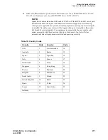
Page 356: ...ch Node Connect Fiber Optic Cables Return to Task List NOTE Always use the Cable Running List that accompanies the system when installing fiber optic cables The following procedure is a typical example of how to cable a system If the cabinets are close together the signal may go through a single directly connected fiber optic cable If the cabinets are far apart it may be easier to connect the cabi...

Page 357: ...k List Connect Standard Reliability CSS Connected System with 1 Switch Node Return to Task List Figure 105 Standard Reliability CSS Connected with 1 Switch Node on page 357 shows typical fiber optic cabling between cabinets The cable between the EI and SNI on the PPN is a pre installed metallic cable H600 278 1 If no running list is available use the outer slots first in alternating order Connect ...

Page 358: ... shows typical fiber optic cabling between cabinets The cable between the EI and SNI on the PPN cabinet is a pre installed metallic cable H600 278 Connect the cables between the PPN cabinet and each EPN cabinet in an alternating port slot order 3 19 4 18 5 17 and so forth Cabinet 1 is a PPN with 1 Switch Node Figure 106 High Reliability CSS Connected with 1 Switch Node Return to Task List Figure n...

Page 359: ...n page 359 shows typical fiber optic cabling between cabinets The cable between port slots 1 and 2 on each switch node is a metallic cable H600 278 Connect the 2 groups of 1 to 15 cables between the PPN and each EPN in an alternating port slot order 20 3 19 4 18 5 and so forth Figure 107 Critical Reliability CSS Connected with 1 Switch Node Return to Task List Figure notes 1 Cabinet 1 PPN with 1 D...
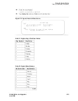
Page 360: ...Install and Connect MCC1 Multicarrier Cabinet Connect Fiber Optic Interconnect Cabling 360 SI Installation and Upgrades June 2004 ...

Page 361: ...ormation task lists and procedures for that activity NOTE It may be more efficient to install each hardware component administer it and test it before going on to install another component As an example install the attendant console using the procedures in Install and Wire Telephones administer it using the procedures in the Administrator s Guide for Avaya Communication Manager 555 233 506 and tes...

Page 362: ... Single Carrier Cabinets Made Easy 362 SI Installation and Upgrades June 2004 ...

Page 363: ...Unpack and Inspect Cabinets on page 364 3 If you cannot get timing from the service provider you may need to install a Stratum 3 clock If this system includes a Stratum 3 clock go to Installing the Stratum 3 Clock on page 693 for instructions 4 Check Circuit Packs on page 364 5 Correct Shipping Errors on page 365 Perform these steps to install the cabinets 6 Position the Cabinets Standard Reliabil...

Page 364: ... people as it may weigh as much as 130 pounds 60 kilograms Use caution to avoid injury 1 Unpack the cabinets from the shipping material and inspect for damage 2 Open and remove the front door and rear panels from the cabinet 3 Verify the label near the circuit breaker on the power supply toward the rear of each cabinet corresponds to the local voltage type DANGER If the label is different than the...

Page 365: ... Earthquake Protection for SCC1 on page 367 Return to this section when finished Perform this step first for all standard reliability cabinet installations 1 Install the cabinet stack processor port network Place Control Cabinet A J58890L on the floor in the position determined when the room layout was planned Set Port Cabinet B J58890H on top of Control Cabinet A Set Port Cabinet C J58890H on top...

Page 366: ...l high or critical reliability cabinet installations 1 Install the Cabinet Stack Processor Port Network Place Control Cabinet A J58890L on the floor in the position determined when the room layout was planned Set Duplicate Control Cabinet B J58890M on top of Control Cabinet A Set Port Cabinet C J58890H on top of Duplicate Control Cabinet B Set Port Cabinet D J58890H on top of Port Cabinet C 2 If a...

Page 367: ...See Figure 108 Cabinet Earthquake Mounting Rear View on page 368 8 Insert a pencil or marker through the holes in the bottom of the cabinet and mark the floor directly beneath each hole 9 Move the cabinet out of the way and drill a hole 0 5 inch 1 27 cm in diameter and 1 5 inches 3 8 cm deep at the locations marked in Step 8 10 Insert a concrete floor anchor STARR part number 3425 into each hole 1...

Page 368: ... Installation and Upgrades June 2004 Figure 108 Cabinet Earthquake Mounting Rear View Figure notes 1 Cabinet 2 Nylon Insulating Washer 2 Required 3 Long Hex Head Bolt 2 Required 4 Stiffener 5 Cabinet Foot 6 Floor Plugs Remove 7 Concrete Floor Anchor 8 Concrete Floor 3 4 5 1 8 2 7 On Off On Off 6 r781851a CJL 030796 ...

Page 369: ...I Installation and Upgrades 369 June 2004 Figure 109 Front Mounting Angle Location Return to Task List Figure notes 1 12 24x1 2 inch Thread Forming Screw 2 Control Cabinet 3 Front Mounting Angle 4 Hex Head Bolt 5 Nylon Insulating Washer 6 Concrete Floor 7 Concrete Floor Anchor 4 1 3 2 5 6 7 r781854a CJL 030896 ...

Page 370: ...he ground plates and cabinet clips are installed later in this procedure Task List Connect the cabinet grounds on the J58890R DC Power Cabinet and the Single Carrier Cabinets 1 Connect DC Power Cabinet Ground on page 370 2 Connect DC Battery Cabinet Frame Ground 3 Connect DC Power Distribution Unit Ground on page 372 4 Connect Single Carrier Cabinet Ground on page 373 Connect DC Power Cabinet Grou...

Page 371: ...n Power Cabinets on page 372 2 Crimp a terminal lug on the each end of the wire The terminal lugs are furnished as part of D 181895 kit of parts 3 At the DC Battery Cabinet attach the 6 AWG 2540 6 4 mm2 wire to the frame ground mounting hole using a pan head slotted screw star washer and hex nut Tighten the screw securely 4 Route the opposite end of the wire to the DC Power Cabinet 5 Attach the 6 ...

Page 372: ...E bar in the DC Power Cabinet and the GRD connector on the DC Distribution Unit See Figure 112 DC Power Distribution Unit Ground on page 373 2 At the DC Power Cabinet connect a the 4 AWG 5 21 mm2 wire to the GROUND DISCHARGE bar 3 Route the opposite end of the wire to the DC Power Distribution Unit and connect the wire to the GRD connector 4 Repeat Steps 2 and 3 for each remaining DC Power Distrib...

Page 373: ...et and the single point ground block on the Control Cabinet bottom cabinet in Figure 113 Single Carrier Cabinet Ground on page 374 2 At the DC Power Cabinet connect the 4 AWG 5 21 mm2 wire to the GROUND DISCHARGE bar 3 Route the wire to Control Cabinet and connect to the single point ground block 4 Repeat for each Control Cabinet in the system room duplicated Control Cabinet and Expansion Control ...

Page 374: ...wing task list to connect DC power Task List Connect the DC power 1 Connect AC Power to DC Power Cabinet on page 379 2 Connect Battery Cabinet on page 380 3 Connect Optional Battery Leads on page 381 Figure notes 1 4 AWG 5 21 mm2 Wire 2 Control Cabinet Cabinet A 3 Single Point Ground Block 4 To Additional Control Cabinets in Same Room 5 DC Power Cabinet 6 Ground Discharge Bar 4 5 1 1 6 dc_rect4 RB...

Page 375: ... Power Distribution Unit on page 378 shows a typical power and ground layout for a DC powered system containing a DC power distribution unit NOTE If the distance between the DC Power Cabinet s is greater than 30 feet 9 m use the Task List Install a J58890CG DC Power Distribution Unit on page 375 Task List Install a J58890CG DC Power Distribution Unit Install on a wall without a plywood backing pla...

Page 376: ...unit aside and install two 12 pan head phillips wood screws rated for at least 50 lbs each in the top position 3 Mount the power distribution unit on the top screws and install the bottom screws through the slots in the power distribution housing Return to Task List DC Power Connections with DC Distribution Unit A 10 foot 3 meter power cord is equipped with the appropriate connectors In the config...

Page 377: ...binet 3 White Wires 4 Green Ground Wires and Black Wires Connect to the 48 VDC Return Bus 5 48 VDC Bus 6 Connect White Wires to Circuit Breakers 7 DC Power Cable H600 436 G1 to Power Connector on Each Cabinet Cut to Length and Crimp a Ring Terminal Onto Each Wire 8 30 Feet 9 m Maximum 9 Route Cables Through Sliding Door 10 Circuit Breaker 11 Supplied 10 32 Screw 10 Star Washer and 10 32 Hex Nut 12...

Page 378: ... of the cabinet stack 4 White Wire connect to Circuit Breaker See inset 5 Green Ground Wires and Black Wire connect to the 48 VDC Return Bus 6 48 VDC Bus 7 Inset 8 12 inches 30 5 cm from floor to DC Power Distribution Unit 9 DC Power Cable to Power Connector on Each Cabinet 10 DC Power Distribution Unit Power Cord route to rear of DC Power Cabinet 11 Route Power Cord Through Sliding Door 12 Circui...

Page 379: ...front of the cabinet when procedures require ALL power to be removed from the cabinet 1 Ensure the associated circuit breakers at the AC power panel are OFF 2 Have an electrician connect AC power leads to the rectifiers using the instructions provided with the rectifiers in the DC Power Cabinet Each rectifier should have its own branch circuit Terminate leads on the AC INPUT terminal block of each...

Page 380: ...LL power to be removed from the cabinet Connect the DC Battery Cabinet to the DC Power Cabinet Figure 117 DC Battery to DC Power Cabinet Connections on page 380 shows how to make typical connections from the DC Battery Cabinet to the DC Power Cabinet Figure 117 DC Battery to DC Power Cabinet Connections Return to Task List Figure notes 1 DC Power Cabinet 2 Connect Red DC Power Cable to 48 VDC Retu...
Page 381: ...1 Set the circuit breakers OFF See Figure 118 Control Cabinet Battery Location Right Side on page 381 2 Connect the battery leads The battery is near the top of the carrier toward the front right The battery leads are located next to the battery and are accessible from the front of the cabinet Figure 118 Control Cabinet Battery Location Right Side Return to Task List Figure notes 1 Battery 2 Batte...

Page 382: ...nect the cabinet grounds on the J58890R DC Power Cabinet and the Single Carrier Cabinets 1 Connect AC Power Ground on page 382 2 Set the Ringer Frequency on page 384 3 Connect the Power Cord into the Power Receptacle on page 384 Connect AC Power Ground Return to Task List 1 Measure and cut a length of 6 AWG 40 4 mm2 wire long enough to reach between the cabinet stack single point ground block and ...

Page 383: ...F and to terminate at the Coupled Bonding Conductor CBC The Coupled Bonding Conductor CBC wires are installed and terminated in Install Telecommunications Cabling on page 403 Figure 119 Typical AC Power and Ground Layout Rear Return to Task List Figure notes 1 Cabinet Stack 1 Control Cabinet A 2 Circuit Breaker 3 AC Power Receptacle 4 Cabinet Stack Single Point Ground Block 5 8 foot 2 5 meters Pow...

Page 384: ... 2 Power down the cabinet 3 Release both latches on the power supply and slide the unit out of the cabinet 4 Observe the ring frequency switch label on the side of the power supply and locate the switch on the bottom 5 Set the ring frequency select switch to the appropriate frequency setting 6 Slide the power supply back into the slot and ensure that both latches snap closed Return to Task List Co...

Page 385: ...Reliability PPN One Cabinet Stack on page 385 High or Critical Reliability PPN Two Cabinet Stack on page 386 High or Critical Reliability PPN Three Cabinet Stack on page 388 Expansion Port Network All Reliability Options on page 389 Standard Reliability PPN One Cabinet Stack Return to Task List 1 Remove the Time Division Multiplexing TDM Bus Terminator AHF110 from Slot 18 of the Control Cabinet Pr...

Page 386: ...vision Multiplexing TDM Bus Terminator from Slot 18 of Control Cabinet A Processor Port Network PPN and move it to Slot 18 of Control Cabinet B See Figure 121 Connections for High or Critical Reliability Systems on page 387 Figure notes 1 AHF110 TDM Bus Terminator Slot 17 2 TDM Local Area Network TDM LAN Pinfield Slot 00 3 TDM Bus Cable WP 91716 L3 4 Port Cabinet Standard Reliability 5 Control Cab...

Page 387: ...r High or Critical Reliability Systems Return to Task List Figure notes 1 AHF110 TDM Bus Terminator Slot 17 2 TDM Local Area Network TDM LAN Pinfield Slot 00 3 TDM bus Cable WP 91716 L3 4 Port Cabinet 5 Control Cabinet A Position 6 AHF110 TDM Bus Terminator Slot 01 7 Slot 18 8 Inter Cabinet Cables ICC A B and C H600 248 G1 9 Inter Cabinet Cable ICC A 10 Inter Cabinet Cable ICC B 11 Duplicated Cont...

Page 388: ...t See Figure 122 Connections for High or Critical Reliability Systems on page 388 2 Connect the supplied TDM Bus Cables WP 91716 L3 as shown Figure 122 Connections for High or Critical Reliability Systems Return to Task List Figure notes 1 AHF110 TDM Bus Terminator Slot 17 2 TDM Local Area Network TDM LAN Pinfield Slot 00 3 TDM bus Cable WP 91716 L3 4 Port Cabinet 5 Control Cabinet A Position 6 AH...

Page 389: ... for High or Critical Reliability Systems on page 389 2 Connect the supplied TDM Bus Cables WP 91716 L3 as shown Figure 123 Connections for High or Critical Reliability Systems Return to Task List Figure notes 1 AHF110 TDM Bus Terminator Slot 17 2 TDM Local Area Network TDM LAN Pinfield Slot 00 3 TDM bus Cable WP 91716 L3 4 Port Cabinet 5 Control Cabinet A Position 6 AHF110 TDM Bus Terminator Slot...

Page 390: ...d for the cabinet carrier jumper connections Verify that the address plug for each port carrier is in the correct location for that carrier See Figure 124 Port Cabinet Address Plug Location Cabinet Rear on page 390 The factory default setting is B callout 2 Figure 124 Port Cabinet Address Plug Location Cabinet Rear Return to Task List Figure notes 1 Address Plug Shown Set to Carrier D 2 Carrier B ...

Page 391: ...anels Also be sure the cables are routed through the channels provided on the rear panels Figure 125 Rear Panel Screw Locations Return to Task List Install Rear Ground Plates Systems with Earthquake Protection Return to Task List Ground plates are installed between stacked cabinets provide the ground connection between cabinets provide radio frequency RF radiation protection and help stabilize the...

Page 392: ...of the cabinet below the top cabinet Slide the mounting plate down to seat on the screws 4 Check all Time Division Multiplexing TDM bus cables and the Inter Cabinet Cables ICC to be sure they are not pinched by the plates 5 Repeat Steps 1 3 until the rear ground plates are installed between all stacked cabinets 6 Do not tighten the screws yet Figure 126 Rear Panel Screw Locations Figure notes 1 Ca...

Page 393: ...lding and Earthquake Protection Return to Task List Ground plates are installed between stacked cabinets provide the ground connection between cabinets provide radio frequency RF radiation protection and help stabilize the cabinets Use the front ground plate instead of the cabinet clip to attach the cabinets to each other Use one front ground plate between two stacked cabinets Figure notes 1 Front...

Page 394: ...ate or Cabinet Clip Side View on page 393 2 At the front of the cabinets align the holes in the bottom of the front ground plate with the holes at the top of the lower cabinet Insert the four supplied 12 24 x 1 2 inch 1 27 cm thread forming screws Do not tighten the screws yet 3 Repeat Steps 1 and 2 until all stacked cabinets are fastened together 4 Tighten all screws securely Figure 128 Rear Grou...

Page 395: ... between each pair of stacked cabinets At the front of the cabinets install a cabinet clip between each pair of cabinets by hooking the clip into the slot of the upper cabinet and snapping the straight leg of the clip into the slot on the lower cabinet See Figure 129 Figure 129 Location of Cabinet Clips Return to Task List Figure notes 1 Control Cabinet 2 Port Cabinet or Duplicated Control Cabinet...

Page 396: ...htguide equipment 3 Connect the fiber optic cable The Customer Service Document CSD provides an Inter Cabinet Cable Running List Each row on the list represents a cable connection Use the running list to determine where to connect each fiber optic cable CAUTION Do not route fiber optic cables and the B25A cables together For standard reliability fiber connections see Figure 132 Connections to Stan...

Page 397: ...otes 1 AHF110 TDM Bus Terminator Slot 17 2 TDM Local Area Network TDM LAN Pinfield Slot 00 3 TDM bus Cable WP 91716 L3 4 Port Cabinet 5 Control Cabinet A Position 6 AHF110 TDM Bus Terminator Slot 01 7 Slot 18 8 Inter Cabinet Cables ICC A B and C H600 248 G1 9 Inter Cabinet Cable ICC A 10 Inter Cabinet Cable ICC B 11 Duplicated Control Cabinet B Position 3 7 7 4 4 11 8 5 1 2 2 9 9 6 2 10 10 tdm_cab...

Page 398: ...Cabinet Cable Connections From Cabinet A To Cabinet B Cabinet Carrier Connection Carrier Connection Processor Port Network PPN J58890L ICC B J58890M ICC B ICC C ICC C Expansion Port Network EPN J58890N ICC A J58890H ICC A ICC B ICC B Figure notes 1 Supplied B25A Cables 2 Loop and Drape Excess Fiber Optic Cable 3 Fiber Optic Cable Sheath 4 Port Cabinet 5 Control Cabinet 3 4 4 4 4 4 4 5 5 1 2 ...

Page 399: ...11 10 9 8 7 6 5 4 3 2 1 18 17 16 15 14 13 12 11 10 9 8 7 6 5 4 3 2 1 3 18 17 16 15 14 13 12 11 10 9 8 7 6 5 4 3 2 1 18 17 16 15 14 13 12 11 10 9 8 7 6 5 4 3 2 1 18 17 16 15 14 13 12 11 10 9 8 7 6 5 4 3 2 1 18 17 16 15 14 13 12 11 10 9 8 7 6 5 4 3 2 1 18 17 16 15 14 13 12 11 10 9 8 7 6 5 4 3 2 1 18 17 16 15 14 13 12 11 10 9 8 7 6 5 4 3 2 1 18 17 16 15 14 13 12 11 10 9 8 7 6 5 4 3 2 1 18 17 16 15 14...

Page 400: ...6 15 14 13 12 11 10 9 8 7 6 5 4 3 2 1 18 17 16 15 14 13 12 11 10 9 8 7 6 5 4 3 2 1 18 17 16 15 14 13 12 11 10 9 8 7 6 5 4 3 2 1 18 17 16 15 14 13 12 11 10 9 8 7 6 5 4 3 2 1 18 17 16 15 14 13 12 11 10 9 8 7 6 5 4 3 2 1 18 17 16 15 14 13 12 11 10 9 8 7 6 5 4 3 2 1 18 17 16 15 14 13 12 11 10 9 8 7 6 5 4 3 2 1 18 17 16 15 14 13 12 11 10 9 8 7 6 5 4 3 2 1 18 17 16 15 14 13 12 11 10 9 8 7 6 5 4 3 2 1 18...

Page 401: ... 3 18 17 16 15 14 13 12 11 10 9 8 7 6 5 4 3 2 1 18 17 16 15 14 13 12 11 10 9 8 7 6 5 4 3 2 1 18 17 16 15 14 13 12 11 10 9 8 7 6 5 4 3 2 1 18 17 16 15 14 13 12 11 10 9 8 7 6 5 4 3 2 1 18 17 16 15 14 13 12 11 10 9 8 7 6 5 4 3 2 1 18 17 16 15 14 13 12 11 10 9 8 7 6 5 4 3 2 1 18 17 16 15 14 13 12 11 10 9 8 7 6 5 4 3 2 1 18 17 16 15 14 13 12 11 10 9 8 7 6 5 4 3 2 1 18 17 16 15 14 13 12 11 10 9 8 7 6 5 ...

Page 402: ...Install and Connect SCC1 Single Carrier Cabinets Connect Time Division Multiplexing Bus Cables 402 SI Installation and Upgrades June 2004 ...

Page 403: ...sneak fuse panels the 110 type hardware and the Cable Slack Manager Station Wiring Design on page 417 Station Circuit Distribution from Equipment Room on page 421 Layout on page 427 Patch Cord Jumper Installation and Administration on page 429 Task List Installing the Telecommunications Cabling 1 Label Control Carrier Cable on page 431 2 Connect Control Carrier Outputs Cable on page 432 3 Connect ...

Page 404: ...ly if required Main Distribution Frame MDF Hardware SYSTIMAX 110 type hardware is used for the Main Distribution Frame MDF 110 type hardware is available in two basic types the 110A and 110P The 110A requires less wall space than the 110P The 110P includes horizontal and vertical cable troughs for managing cross connect cables The system is connected to the MDF with the supplied B25A male to femal...

Page 405: ...able 25 Pair Cable Trunk Circuit Pack Line Circuit Pack 25 Pair Cable To Network Intrface Yellow Field Figure notes 1 Rear of Port Cabinet 2 Main Distribution Frame MDF 3 Port Distribution Field Purple Field 4 Station Distribution Field White Field 5 Trunk Auxiliary Field 6 Purple Field 7 Yellow Field 8 Green Field 9 Satellite Closet 10 Auxiliary Cabinet Yellow Field 11 White Field 12 Blue Field 1...

Page 406: ... concentrator cables Also 25 pair cables can be used to terminate trunk circuits from the system with each trunk circuit pack connecting to one 25 pair row of the 110 type terminal block Each terminal block row can terminate twenty four 1 pair eight 3 pair or twelve 2 pair trunks The yellow field provides cross connect terminals for all miscellaneous leads from the system such as alarm monitors em...

Page 407: ...om two connectors on the system to one 25 pair connector on a terminal block The yellow field auxiliary field terminates all 25 pair cables from the auxiliary cabinet and the Processor Interface The yellow field is located in the lower right hand corner of the distribution field The white field station field terminates the station wiring The white field indicates 3 pair station circuits eight circ...

Page 408: ...ge 408 shows a typical SCC1 Single Carrier Cabinet installation using 110A type terminal blocks and Figure 138 Typical 110P Type Terminal Blocks MCC1 on page 409 shows a typical Multi Carrier Cabinet installation using 900 pair 110P type terminal blocks Figure 137 Typical 110A Type Terminal Blocks SCC1 Figure notes 1 Single Carrier Cabinets Stacked SCC1 2 Z113A Cable Slack Manager 3 25 Pair Cable ...

Page 409: ...onnections information outlets and cables The labels are color coded to identify system wiring Green To Central Office CO Purple To system ports Yellow To auxiliary equipment and miscellaneous system leads Blue To information outlets White From Main Distribution Frame to satellite locations 3 pair Figure notes 1 Multi Carrier Cabinet MCC1 2 Z113A Cable Slack Manager 3 25 Pair Cable to System Cabin...

Page 410: ...comply with local safety standards Sneak current protectors must have a maximum rating of 350 mA and a minimum voltage rating of 600 V or as required by local regulations The following devices protect the system from over voltages Analog trunks use the 507B sneak protector or equivalent Over voltage protection is normally provided by the local telephone company Analog voice terminals use one of th...

Page 411: ... and two cables The SCP 110 protectors are used with 110 type hardware and on the 507B Sneak Fuse Panel The SCP 110 Protectors can be ordered separately and installed on the 157B connecting block Fifty protectors are required per block Cable Installation NOTE To route the cables from the rear of the SCC1 stack or MCC1 to the MDF use the Install Cable Slack Managers on page 441 procedure Also see C...

Page 412: ...Cable Routing to Bottom Terminal Blocks on page 415 show typical cable routing from the cabinet to the top and bottom of the MDF respectively Use these guidelines when routing cables from the cabinet to the MDF Following these guidelines will maximize use of the cable slack managers and make future cabling additions and changes easier Connect each port cable at the cabinet and then route it along ...

Page 413: ... administered to make contact when a major minor or warning alarm condition occurs in the system Trunk Cables Among Network Interface Sneak Fuse Panel and Cabinet The 1 pair of Central Office CO trunks are installed by the network provider in the green field Up to 24 pairs may be terminated on each row of the 110 type terminal block Tie trunks also appear in the green field with up to eight 3 pair...

Page 414: ... 1D20 1E1 1E20 Building Field Identified Floor Field Identified Auxiliary Cable Field Identified Site or Satellite A F and or Field Identified r758424b MMR 052996 Figure notes 1 Main Distribution Frame 2 AC Power Cord AC Powered Cabinets Only 3 Cable Slack Manager Number 1 4 Trunk Auxiliary Field 5 Station Distribution Field 6 Cable Slack Manager Number 2 7 Cable Slack Manager Number 3 8 System Ca...

Page 415: ...ng cable and terminated at the CBC terminal bar at the Main Distribution Frame MDF A minimum of 12 inches 30 48 cm spacing must be maintained between the CBC and other power and ground leads The 10 AWG 25 2 5 mm2 wire must be long enough to reach the telecommunications cables at the rear of the system cabinets follow these cables to the MDF and to terminate at the CBC r758432b MMR 052996 Figure no...

Page 416: ...k is 10 81 inches 27 4 cm wide however no horizontal patch cord troughs are used and the blocks are shorter than 110P type terminal blocks This allows the 110A type terminal blocks to be stacked Therefore the 110A type hardware requires less space than the 110P type hardware on a per station basis Cable Slack Manager A Cable Slack Manager is 32 inches 81 3 cm wide Slack managers are commonly used ...

Page 417: ...page 419 25 pair station cable Use between the equipment room and site satellite locations or adapters Use an A25D cable male to male between the equipment room and satellite closet Use a B25A cable between the equipment room and site closet or adapter Multiple 25 pair station cable Use between the equipment room and site satellite locations or adapters This cable consists of individually sheathed...

Page 418: ...inal blocks in the equipment room or satellite closet and the information outlets require push on connections Closets Site Locations Site locations are closets that provide a point in the station wiring for the administration of remote powering Adapters are used at site locations to terminate the 25 pair station cables and provide connection points modular jacks for power adapters and 4 pair stati...

Page 419: ...d on the same terminal block The 110A type terminal block that can be used is the 110AE1 75FT It must be field terminated to both the white and blue fields The 300 pair 110P type terminal blocks that can be used are 110PE1 300CT FT 25 pair connector on the white field and field terminated on the blue field 110PE1 300FT Field terminated on both the white and blue fields The 900 pair 110P type termi...

Page 420: ... 258A and BR2580A Adapters Figure 146 356A Adapter 3 4 4 1 2 crdfadp CJL 101596 Figure notes 1 BR2580A Adapter 2 258A Adapter 3 25 Pair Male Ribbon Connector 4 4 Pair Modular Jacks 8 Pins Figure notes 1 356A Adapter 2 4 Pair Modular Jacks 6 pins each connected to 25 pair ribbon connector crdf356 CJL 101296 1 2 ...

Page 421: ...dapter as shown in Figure 147 4 Pair Circuit Distribution and Connectivity on page 422 The 4 pair station cables connect the adapter to the information outlets The 4 pair station cables can be run directly from the equipment room to the information outlets if 4 pair terminal blocks are used in the distribution field See Figure 148 4 Pair Run to Equipment Room or Satellite Location on page 422 The ...

Page 422: ...Pair Connecting Blocks 4 Purple Field 5 Blue Field 6 Patch Cord or Cross Connect Jumpers 7 To System Cabinet Three Pair Modularity 8 B25A Cable 9 Connectorized Staggered Finger Multiple 25 Pair Cable 10 258A or BR2580A Adapter 11 Information Outlet 12 4 Pair Circuit 13 DIW Station Cable D Inside Wire Figure notes 1 Station Side of MDF or Satellite Location 2 4 Pair Circuit 3 Blue Field 4 DIW Stati...

Page 423: ...oom or Satellite Location 8 7 1 9 10 11 r758532a CJL 031196 2 4 3 6 5 Figure notes 1 Part of MDF 2 3 Pair Connecting Blocks 3 4 Pair Connecting Blocks 4 Purple Field 5 Patch Cord or Cross Connect Jumpers 6 Blue Field 7 To System Cabinet 3 pair modularity 8 A25D Cable 9 258A or BR2580A Adapter 10 Information Outlet 11 4 Pair Circuit DIW station cable D Inside Wire ...

Page 424: ... 1 Part of MDF 2 3 Pair Connecting Blocks 3 Purple Field 4 White Field 5 Patch Cord or Cross Connect Jumpers 6 To System Cabinet 3 Pair Modularity 7 A25D Cable 3 Pair Circuits 8 B25A Cable 9 Connectorized staggered finger Multiple 25 Pair Cable 10 4 Pair Connecting Blocks 11 Blue Field 12 258A or BR2580A Adapter 13 Information Outlet 14 4 Pair Circuit DIW Station Cable D Inside Wire 15 Part of Sat...

Page 425: ...le Field 4 Blue Field 5 Patch Cord or Cross Connect Jumpers 6 To System Cabinet 3 Pair Modularity 7 B25A Cable 8 3 Pair Circuits 9 356A Adapter 10 Information Outlet 11 3 Pair Circuit in 4 Pair Wire 12 DIW Station Cable D Inside Wire Voice and Data Terminals Type Multi button Electronic Telephone MET sets 10 20 30 Button Voice Analog 500 2500 2554 2500 DMGC 2500YMGK S203A Speakerphone Analog voice...

Page 426: ...ss Communications Systems BCS PC PBX platform digital PC ISDN platform BRI Data Consoles 301A Attendant Console 302A1 Enhanced Generic 1 Console 602A1 ACD Console CallMaster digital communications terminal Data and voice ZE01A Expansion Module for 8434Dx Voice and Features Cordless Hybrid MDW 9000 TransTalk 9000 MDC 9000 Voice DCP Data interface Constellation Automatic Call Distribution ACD data t...

Page 427: ... page 428 Sizing 25 Pair and Multiple 25 Pair Station Cables on page 428 3 Pair Station Cable Circuits on page 428 4 Pair Station Cable Circuits on page 428 Information Outlet Locations The customer or marketing representative must provide floor plans showing the information outlet locations and types flush or surface mounted required The floor plans must also show a complete overview of all condu...

Page 428: ...ters B25A cables are required at the equipment room or satellite location to connect the staggered finger cables to the 110 type terminal blocks Use the following information to determine the cable size cable pairs required for either 3 pair or 4 pair circuits Note the length and size on the floor plan to aid in the ordering and installation of the station cables 3 Pair Station Cable Circuits To d...

Page 429: ...s entry is all that is required The white label identifying the terminal block row associated with circuits 17 to 24 connects to an identically labeled terminal block row at the satellite closet See Figure 153 Example 3 Pair Labeling to Information Outlet on page 430 This is always the case for either 1 point or 2 point administration The satellite symbol must be installed at all connection points...

Page 430: ...f5pr CJL 103096 Figure notes 1 Equipment Room 2 Satellite Location 3 Work Location 4 White Row on 110 Terminal Block 5 Purple Row on 110 Terminal Block 6 Blue Row on 110 Terminal Block 7 Central Location for Terminals 1 through 6 8 D Inside Wire Cut Down to Connecting Block 9 258A Adapter 10 Information Outlet 11 Voice Terminal 12 To Port Connector on Cabinet Cabinet 1 Carrier A Slot 03 ...

Page 431: ...signed 110 type terminal block row 2 On the control carrier cable place a yellow auxiliary label on the connectors at each end of the cable 3 Write AUX on each label Figure notes 1 Equipment Room 2 To Central Location for Terminals 1 through 6 3 Blue Row on 110 Terminal Block 4 Purple Row on 110 Terminal Block 5 To Port Connector on Cabinet Cabinet 1 Carrier A Slot 03 6 258A Adapter 7 D Inside Wir...

Page 432: ... cables between the network interface and sneak fuse panels 2 Connect A25D cables from the sneak fuse panels to the 110 type terminal block connectors in the green field 3 Connect patch cords jumper wires from the terminal block in the green field to the associated terminal block in the purple field 4 Connect the single fingered end of the concentrator cables to the 110 type terminal block connect...

Page 433: ...with jumper wires to establish 3 pair modularity To connect the trunk pairs to the purple field 1 Connect B25A cables between the network interface and the sneak fuse panels See Figure 156 3 Pair Modularity for Trunk Pairs for 1 Pair Trunks on page 434 2 Connect A25D B25A cables from the sneak fuse panels to the 110 type terminal block type connecting block connectors in the green field NEW796 THC...

Page 434: ...l block rows in the purple field for 1 pair Central Office CO trunks or in Figure 157 3 Pair Modularity for Trunk Pairs for 3 Pair Tie Trunks on page 435 for 3 pair tie trunks Figure 156 3 Pair Modularity for Trunk Pairs for 1 Pair Trunks 1 2 3 4 5 6 7 8 1 4 7 10 13 16 19 22 1 4 7 10 13 16 19 22 1 4 7 10 13 16 19 22 9 10 11 12 13 14 15 16 17 18 19 20 21 22 23 24 r758425b MMR 031496 Figure notes 1 ...

Page 435: ...on the labels so the cabinet connector retainers do not cover them 3 At the rear of the cabinet connect 1 end of the connector cable to the assigned connector 4 Route the cable down the rear of the cabinet through the cable slack manager and to the MDF 5 At the MDF connect the other end of the cable to the assigned terminal connecting block connector 6 Store the cable slack in the cable slack mana...

Page 436: ... rings on the wall between the cable slack manager and the terminal connecting blocks mounted on the MDF 2 Install a self sticking port label on the rear of each connector on the B25A connector cable See Figure 141 Self Stick Label on 25 Pair Cable Connector on page 414 3 Labels should be positioned so they will not be obscured by the cabinet connector retainers 4 At the rear of the Auxiliary cabi...

Page 437: ...e wall 4 Slide the bottom terminal block ft onto the mounting screws and mark the upper mounting screw locations 5 Remove the terminal block and partially install the upper mounting screws 6 Place the terminal block on the mounting screws and tighten the screws 7 If installing a vertical patch cord trough partially install the first screw for the patch cord trough on the line 7 8 in 2 2 cm to the ...

Page 438: ...stration 438 SI Installation and Upgrades June 2004 Figure 159 110A Type Terminal Blocks 300 Pair Figure notes 1 4 ft 1 22 m 2 6 6 ft 2 m 3 7 68 in 19 5 cm 4 7 8 in 2 22 cm 5 5 31 in 13 5 cm 6 47 5 in 120 6 cm 7 Horizontal Line 8 AC Power Strip 9 Floor Line r758420b MMR 031496 ...

Page 439: ...pparatus Mounting Frame See Figure 161 1110A2 and 1110C1 Apparatus Mountings on page 440 Each 1110A2 provides the space to mount 5 terminal blocks patch cord troughs on each side of the frame A cable support structure apparatus mounting 1110C1 mounts directly on top of the 1110A2 and provides support for all cables routed to and from the frame See Apparatus Mounting Frame Information on page 440 r...

Page 440: ...us Mountings Return to Task List r781401 LJK 040896 Figure notes 1 1110C1 Apparatus Mounting 2 1110A2 Apparatus Mounting 3 76 in 193 cm 4 88 5 in 225 cm 5 43 5 in 110 5 cm Apparatus Mounting Frame Information Code Number Description 1110A2 Apparatus Mounting Frame 1110C1 Cable Support Assembly 1110A1 End Dress Panel 2110A1 Top Dress Panel 2110B1 Bottom Dress Panel ...

Page 441: ...d on an uneven floor shims may be required for leveling and to assure proper fit of the covers Holes are provided in the sides of the base for bolting cable slack manager together Bolts and shims must be obtained locally 4 The system cables will route through the cable slack manager as shown Complete cable routing is covered later in this chapter Cable clamps are required in installations with cab...

Page 442: ... Figure 163 Cable Routing Through Cable Slack Manager SCC1 Return to Task List Figure notes 1 Top of System Cabinets 2 Cable Clamps 3 Cable Ties Optional 4 Power Cord 5 Cable Slack Manager 6 Cable Slack Manager Cover Removed 7 Main Distribution Frame MDF 8 Route Cables Along Path Shown 9 Port Cables 3 5 1 2 r758155 CJL 031496 4 ...

Page 443: ...he panel against the mounting surface and mark the mounting screw locations Drill pilot holes at the marked locations and partially install a locally obtained 12 x 3 4 inch screw into the two bottom mounting slots 3 Slide the sneak fuse panel onto the mounting screws and tighten the screws securely 4 Install a locally obtained 12 x 3 4 inch screw into the top two mounting slots and tighten securel...

Page 444: ...pgrades June 2004 Return to Task List Sneak Fuse Connector Pinout Connector Pin Numbers Pair Fuse Number 26 1 1 27 2 2 28 3 3 29 4 4 30 5 5 31 6 6 32 7 7 33 8 8 34 9 9 35 10 10 36 11 11 37 12 12 38 13 13 39 14 14 40 15 15 41 16 16 42 17 17 43 18 18 44 19 19 45 20 20 46 21 21 47 22 22 48 23 23 49 34 24 50 25 25 ...

Page 445: ... the pairs reduces potential differences in terminating equipment 1 Cut a 10 AWG 25 2 5 mm2 wire long enough to reach from the system s single point ground block or DC power cabinet Ground Discharge Bar to the MDF CBC block 2 Connect one end of the 10 AWG 25 2 5 mm2 wire to the single point ground block or Ground Discharge Bar 3 Route the wire next to the 25 pair cables connecting to the trunk aux...

Page 446: ...Bonding Conductor CBC Terminal Block 3 Tie Wraps 4 Cable Shield or Six Spare Pairs 5 Ground on Carbon Block Protector or Equivalent 6 Trunk Cable to Network Interface 7 10 AWG 25 2 5 mm2 Wire 8 To Network Cabinets 9 Battery Plant Ground Discharge Bar for Single Point Ground 10 Cross Connect Ground Block 11 Main Distribution Frame MDF 12 To Other Cross Connect Ground Blocks 13 Approved Ground 14 Co...

Page 447: ... Task List Setting up the PC and Administering the System 1 Access the System on page 452 2 Activate the System on page 460 3 Administer the System on page 463 If necessary administer the Circuit Packs See Administering the Circuit Packs on page 449 for general information 4 Reboot High Reliability System MCC1 only on page 476 5 Enable Duplication and Boot Critical Reliability System Avaya DEFINIT...

Page 448: ...and appears on the screen The ACTION specifies the operation desired Examples include add duplicate change remove display list and save OBJECT is the second part of the command and specifies the particular object to be administered Typical entries are hunt group coverage path and station QUALIFIER is the last part of the command It is one or more words or digits used to further identify or complet...

Page 449: ...included in the hardware It is not necessary to fill in the Circuit Packs screen if the circuit packs are installed at the time of administration For initial installation assign circuit packs to slots using the hardware configuration layout record from the factory or Customer Services Organization Do not arbitrarily assign circuit packs to slots For r If the carrier type administered on the Cabine...

Page 450: ...ack types that may be administered in those slots for each combination of Cabinet Carrier Carrier Type in an si configuration Code Enter the circuit pack code TN followed by a 3 or 4 digit number If there is a physical circuit pack installed in the slot the entry must match that of the circuit pack If there is equipment administered on a slot the equipment must be removed from the circuit pack bef...

Page 451: ...ocated at the top right portion of the front panel 2 Hold the Boot Shutdown button in until the LCD display flashes the message MSHUT 3 Release the Boot Shutdown button NOTE The DEFINITY AUDIX System takes about five minutes to shut down The heartbeat indication on the display continues to flash change circuit packs Page 1 of 5 CIRCUIT PACKS Cabinet 1 Carrier A Carrier Type processor Slot Code Sf ...

Page 452: ...ots This sequence may show an MD or MJ ADX alarm in the display until the system has powered up When the system has completed its power up sequence the DEFINITY AUDIX System display reads ADX Access the System Return to Task List To access the system you first install Avaya Site Administration software on the PC and then connect to the Avaya Media Gateway Select the correct procedures for this ins...

Page 453: ...ports a whole range of other features including the graphically enhanced DEFINITY interface GEDI and Data Import For more information refer to the Help Guided Tour and Show Me accessed from the Help menu Minimum requirements to run Avaya Site Administration Operating systems MS Windows 95 MS Windows 98 MS Windows NT 4 0 MS Windows 2000 Processor RAM 486SL 66 16 MB Pentium 32 MB Pentium 64 MB Penti...

Page 454: ...ctive connector Figure 167 A typical direct connection Free serial ports One free serial port capable of 9600 bps operation is required for a connection to each serial device ADU modem data module or direct connection to a Avaya Media Gateway We recommend that PCs have at least a 16550A UART or 16550A UART simulator capable of 56 kbps DTE speed connections USB and internal modems should emulate th...

Page 455: ...r 7400B data module use a 4 wire digital line circuit pack With the 8400B data module use a 2 wire digital line circuit pack In place of a 7400B data module you can use a 7400A data module If you do see Set the Data Module to DCE Mode on page 458 2 Wire the digital line circuit pack to the wall jack as follows For a 7400B wire to the second and third pair of the wall jack For an 8400B wire to the ...

Page 456: ...aya Media Gateway through a modem 1 Connect the computer to the modem 2 Connect an analog telephone line to the leftmost analog line port on the modem 3 Make sure that the modem s DIP switches are set as shown in U S Robotics Modem DIP Switch Settings on page 457 4 Plug the modem into an AC power outlet 5 Turn on the modem Figure notes 1 Avaya Media Gateway 2 Digital line circuit pack 3 B25A 25 pa...

Page 457: ...5A cable RS 232 9 25 pin adapter if needed 3 Analog modem 4 7 ft 2 m D2W modular cord 5 103A or Avaya modular wall jack 6 Main distribution frame MDF 7 Analog line circuit pack 8 Analog trunk circuit pack Packet data line r Data line r 9 Avaya Media Gateway 10 B25A cable 11 Analog line U S Robotics Modem DIP Switch Settings Dip Switch Setting Description 1 UP DOWN Data Terminal Ready normal Data T...

Page 458: ...icating with the Avaya Media Gateway Check the wiring at the MDF wall jacks and data module Return to Task List Add a Data Module to the Switch Return to Task List 1 Add the data module administratively to the switch by typing add data module number or add data module next and pressing Enter 2 In the Type field type pdm and press Enter 3 In the Port field type the location of the digital line circ...

Page 459: ...ot a null modem cable 6 Set the operating mode Type of Data Module How to Test and Troubleshoot 8400B The red LED should be steady on If the red and green LEDs are blinking the unit is not communicating with the Avaya Media Gateway Check the wiring at the MDF wall jack and the 8400B 7400B The Power and TR LEDs should be steady on If the Power and Data LEDs are blinking the unit is not communicatin...

Page 460: ...t 2 If any switches were set in step 1 cycle the power to the data module so that the firmware can read the new switch settings Return to Task List Activate the System Return to Task List NOTE To prevent unnecessary trouble tickets do not enable the system alarms Alarm Origination feature until all installation and administration procedures are completed CAUTION It may be necessary to reseat circu...

Page 461: ... Return to Task List 1 Insert the translation card into processor circuit pack Return to Task List Install Removable Media MCC1 only Return to Task List 1 Insert the formatted removable media label facing left into the optical drive see Figure 170 TN2211 Optical Drive on page 461 NOTE Make sure the formatted removable media is not write protected see Figure 171 Make sure the disk is not write prot...

Page 462: ... red lights may be on but will be turned off by other procedures in this chapter Power Up DC Powered System Return to Task List 1 At the DC Battery Cabinet if installed set the circuit breaker to ON 2 At the DC Power Cabinet set the circuit breakers on the associated rectifiers ON This starts the system initialization and test Some red LEDs may be on but are turned off by other procedures in this ...

Page 463: ...nge certain options These sections are not intended to replace or modify the instructions provided in the Administrator s Guide for Avaya Communication Manager 555 233 506 INTERNAL REGISTER TEST PASSED LOOP DATA TEST PASSED DUART TEST PASSED ROM CHECKSUM TEST PASSED CONTROL STATUS TEST PASSED DCACHE TEST PASSED ICACHE TEST PASSED WRITE BUFFER TEST PASSED BTO TEST PASSED MEM CONFIG TEST PASSED MEMO...

Page 464: ... the dadmin password 2 Verify the screen displays password 3 Type the default password and press Enter For security reasons the password is not displayed as it is typed The system verifies a valid login and password name were entered 4 If an invalid login or password name was entered the screen displays login incorrect In this case repeat the procedure using the correct login and matching password...

Page 465: ... y and submit the form 8 Type save translation and press Enter After the translations have been copied about 10 minutes the system returns an error code which must be a zero otherwise the translations are not copied 9 Type reset system 3 preserve license or reset system 3 no preserve license since the License File has been saved in translations and press Enter New simplex and upgraded G3r only 1 T...

Page 466: ...ructions in the Deliver to G3r G3si G3csi chapter of the RFA Job Aid deliver the License File NOTE This procedure sends the License File to the switch and installs it b If the system has IP endpoints registered and you unplugged the Ethernet cable from the TN799 C LAN circuit pack replug the cable This re registers the IP endpoints No connection between the switch and RFA a Go to the RFA website a...

Page 467: ... field optional type a valid extension NOTE All calls are not rerouted to this number only calls to this number get through This number cannot be a hunt group or ACD number 5 Press Enter to save the changes Return to Task List Change Site Data MCC1 only Return to Task List This screen initializes the building floor and color data to make them available later in help messages that refer to site 1 T...

Page 468: ...k If set to y the cabinet has a remote si processor that provides a backup if the links to this cabinet are inoperative Survivable Remote Processor ID Displays only if the Survivable Remote EPN field is y Enter the product ID assigned to the remote si This allows DEFINITY Fault Management to know which machine is the backup for this cabinet The entry in this field cannot be the same as the entry i...

Page 469: ... number or port network number Duplicate The location for the duplicate of a switch node Only displays when administration of PNC Duplication is enabled If the Carrier Type is dup switch node the field displays the three character carrier address of the duplicate The first two characters represent the cabinet number the third character represents the carrier A through E This is a display only fiel...

Page 470: ... mode is mu Law Other items eventually need to be entered on this screen but this is all that must be done to turn the red alarm LEDs off 3 If all red LEDs do not go off reseat unplug and reinsert any port circuit packs displaying red LEDs CAUTION To avoid a disk crash never reseat the DEFINITY AUDIX System without first shutting it down Shut down the DEFINITY AUDIX System and allow the disk to co...

Page 471: ...necting to port circuit packs is installed Normally some alarms will be logged when power is applied to the system but should be resolved quickly If no equipment is connected to the port circuit packs alarms associated with these ports can take up to four hours to log but will clear automatically after all equipment is installed and operating correctly Table 16 Country Codes Country Code Country C...

Page 472: ...word if you want CAUTION After changing the password safeguard the new password so no unauthorized administration changes can be made DO NOT REVEAL this password to any unauthorized person Passwords are changed using the PASSWORD ADMINISTRATION screen See Figure 176 Typical Change Password Screen on page 473 1 Verify the screen displays command 2 Type change password craft and press Enter 3 Verify...

Page 473: ...ask List You can set up to 15 customized daylight savings rules See Figure 177 Typical Daylight Savings Time Rules on page 474 If you have switches in several different time zones you can set up rules for each A daylight savings time rule specifies the exact time when you want to transition to and from daylight savings time It also specifies the increment at which to transition 1 Type change dayli...

Page 474: ...ioned on the Hour field Type the current hour for a 24 hour clock See Table 19 Conversion to 24 Hour Clock on page 476 Press Tab to move to the next field 8 The cursor is positioned on the Minute field Type current minute 0 through 59 Seconds cannot be set 9 Type standard or daylight savings in the Type field 10 Type the rule number in the Daylight Savings Rule field 11 Press Enter when the inform...

Page 475: ... Typical Date and Time Screen Table 17 English Day of the Week Names Day Number Day Name 1 Sunday 2 Monday 3 Tuesday 4 Wednesday 5 Thursday 6 Friday 7 Saturday Table 18 English Month Names Month Number Month Name 1 January 2 February 3 March 4 April 5 May 6 June 7 July 1 of 2 DATE AND TIME DATE Day of the Week Tuesday Month November Day of the Month 3 Year 1998 TIME Hour 20 Minute 30 Second XX Typ...

Page 476: ...hat handshake shadowing and refreshed are all shown to be either yes or on 8 August 9 September 10 October 11 November 12 December Table 19 Conversion to 24 Hour Clock Standard Time Standard Time 12 Hour 24 Hour 12 Hour 24 Hour 12 00 midnight 0000 12 00 noon 1200 1 00 am 0100 1 00 pm 1300 2 00 am 0200 2 00 pm 1400 3 00 am 0300 3 00 pm 1500 4 00 am 0400 4 00 pm 1600 5 00 am 0500 5 00 pm 1700 6 00 a...

Page 477: ... have a dadmin login and password you can use them instead of craft and the craft password 2 Type display system parameters country options and press Enter to verify the system s companding mode for its local stations is set to the desired value usually A Law for Europe and mu Law for North America and Japan 3 If necessary type change terminal parameters and press Enter to change the default syste...

Page 478: ...liability systems Return to Task List Save Translations Avaya DEFINITY Server r Return to Task List This command copies the current system translations onto the translation card or removable media For standard reliability systems one removable media for backup is required For high or critical reliability systems two removable media for backup are required To copy the current system translations on...

Page 479: ...tch connectivity through The INADS line An IP address NOTE ART is not accessible from the public internet outside the Avaya intranet firewall 1 At your laptop PC direct your browser to this URL http spiexp1 eng avaya com 8000 cgi bin ART ARTstart cgi You can also save this URL in your Favorites or Bookmarks list The ART User Menu displays 2 Click on the Register a Product button The Enter Network ...

Page 480: ...tep 4 above If you entered an incorrect number a Click on the Abort Upgrade Registration Session button at the bottom of the screen CAUTION DO NOT exit your browser to abort the session This can result in an incomplete upgrade registration b Return to the ART User Menu page to begin a new session If the FL Sold To number matches multiple customers in the database ART displays the name and address ...

Page 481: ...mplete alarm destination telephone number including any dialing prefix for example 9 or 9 The default value in this field is the TSO Denver number 18005353573 17 Click on the Continue Registration button at the bottom of the page ART begins automatically registering the product and displays progress messages to indicate the current status CAUTION DO NOT exit your browser or click on the Refresh Ba...

Page 482: ...Bring the System Online Task List Administer the System 482 SI Installation and Upgrades June 2004 Log off the System Return to Task List 1 Type logoff The login prompt appears on the screen ...

Page 483: ...Carrier Cabinets or to an MCC1 Multi Carrier Cabinet making up one port network A port network is defined as a group of cabinets connected together with one TDM bus Task List Test the System CAUTION To prevent unnecessary trouble tickets do not enable the system alarms Alarm Origination feature until all installation and administration procedures are completed 1 Check System Status for Each Cabine...

Page 484: ...sole on all circuit packs and optionally on customer designated voice terminals More detailed information is available here for Attendant Console LEDs on page 484 Terminal Alarm Notification on page 484 Circuit Pack LEDs on page 485 DS1 Converter Circuit Pack LEDs on page 485 SPAN LEDs on page 485 LEDS on Standby Components on page 485 Attendant Console LEDs The console has 2 red LEDs labeled ALM ...

Page 485: ...D is in one of the following states Solid on yellow Facility is operational and alarm free Blinking yellow for 2 seconds off 0 1 seconds Facility is operational and alarm free AND is carrying the control channel facility A or B only Solid on red Facility is alarmed Solid off Facility is not administered or has been busied out LEDS on Standby Components In high and critical reliability systems dupl...

Page 486: ...o lit briefly when a circuit pack is inserted or reset If the circuit pack passes its initialization tests the LED goes out Green Testing The system is currently running tests on this circuit pack as part of background maintenance or demand testing This LED is also lit during initialization tests when a circuit pack is inserted or reset Yellow Busy The circuit pack is currently in use by the syste...

Page 487: ... frame or fiber loss of signal 0 5 second 0 5 second In frame fiber channel down The fiber channel communicating between the DS1 Converter and the other fiber endpoint EI or SNI is down 1 second 1 second In frame control channel down The control channel between the 2 DS1 Converters in the DS1 Converter complex is down 2 seconds 0 2 second No response from SPE The SPE is not acknowledging messages ...

Page 488: ...The cabinet carrier slot numbers for the fiber optic cables are listed For example 01A01 in Figure 181 Sample System Status Screen for Cabinet 1 Page 1 of 3 on page 488 refers to cabinet stack 01 carrier A and slot 01 in Page 2 section 1 Tone Clock in for Cabinet 2 Page 2 section 2 TDM in for Cabinet 2 Page 2 section 3 EXP LINK in for Cabinet 2 status system all cabinets Page 1 of 3 SPE A SYSTEM S...

Page 489: ...cks Do not attempt to correct any problems until after the diagnostic tests that you run later in the system tests 3 Note any boards with a VINTAGE column entry of NO BOARD or CONFLICT NOTE A u indicates unassigned ports and a number indicates the port has been translated status system all cabinets Page 2 of 3 SPE A SYSTEM STATUS CABINET 2 SELECT SPE ALARMS TONE SERVICE SYSTEM SYSTEM SPE MODE SWIT...

Page 490: ...ork PPN 1 list configuration all Page 1 SYSTEM CONFIGURATION Board Assigned Ports Number Board Type Code Vintage u unassigned t tti p psa 01A01 EXPANSION INTRFC TN570D 000001 01A03 DID TRUNK TN459B 000004 u u u u u u u u 01A04 DID TRUNK TN436B 000004 u u u u u u u u 01A07 TIE TRUNK TN439 000004 u u u u 01A09 ANNOUNCEMENT TN750 000007 01 02 03 04 05 06 07 08 09 10 11 12 13 14 15 16 01B01 EXPANSION ...

Page 491: ...t test tdm port network 1 TEST RESULTS Port Maintenance Name Alt Name Test No Result Error Code PN 01A TDM BUS 294 PASS PN 01A TDM BUS 296 PASS PN 01A TDM BUS 297 ABORT 1005 PN 01B TDM BUS 294 PASS PN 01B TDM BUS 296 ABORT 1005 PN 01B TDM BUS 297 PASS Command successfully completed Command test tone clock 1a TEST RESULTS Port Maintenance Name Alt Name Test No Result Error Code 01A TONE BD 46 PASS ...

Page 492: ...tem cabinet number 1 44 and press Enter or If Single Carrier Cabinet SCC1 type status system all cabinets and press Enter 2 Verify the screen displays test results similar to Figure 187 Example System Status Report for All Cabinets on page 493 3 Note the MODE of SPE 1A and 1B 4 Type refresh spe and press Enter Command successfully completed displays 5 Type reset system interchange and press Enter ...

Page 493: ...s the cabinet carrier and slot for an Expansion Interface EI circuit pack in the system and press Enter NOTE Labels on the port network and carrier and on the strip under the circuit pack contain this information 2 Verify the screen displays test results similar to Figure 188 Sample Test Results for Expansion Interface Board 2A01 on page 494 This example is for board 2a01 3 If any result is FAIL c...

Page 494: ...e connectors of the TDM bus cables in Processor Port Network PPN 2 4 Repeat these steps for each Expansion Port Network EPN to check the TDM bus cables Figure 189 Sample Test Results for TDM Bus Port Network 2 Return to Task List TEST RESULTS Port Maintenance Name Alt Name Test No Result Error Code 02A01 EXP INTF 237 PASS 02A01 EXP INTF 238 PASS 02A01 EXP INTF 240 PASS 02A01 EXP INTF 241 PASS 02A0...

Page 495: ...r for the Standby Tone Clock Press Enter 3 If Multi Carrier Cabinet MCC1 type status system cabinet number 1 44 and press Enter or If Single Carrier Cabinet SCC1 type status system all cabinets and press Enter 4 Verify the duplicated Tone Clock is active using the information displayed on the screen If any problems are indicated check the TDM cables in the associated Expansion Port Network EPN Ret...

Page 496: ...net cables ICC in the associated Expansion Port Network EPN Figure 190 Sample of System Status before Expansion Link is Set Figure 191 Sample of System Status after Expansion Link is Set Return to Task List status system all cabinets SYSTEM STATUS CABINET 1 EMERGENCY SELECT SERVICE CABINET TRANSFER SWITCH EXP LINK STATE MODE TYPE 1A unavail 01A01 02A01 in standby ESCC 1B auto on 01B01 02B02 in act...

Page 497: ... configuration all and press Enter 2 Verify all circuit packs are listed in the reports Refer to the Maintenance for Avaya DEFINITY Server SI 555 233 123 documentation to resolve any discrepancies Save Translations if Required Return to Task List If any administration changes have been made save and make a back up copy of the translations ...

Page 498: ...Test the System LED Indicators 498 SI Installation and Upgrades June 2004 ...

Page 499: ...ls on page 500 Analog Tie Trunk Example on page 506 Digital Tie Trunk Example on page 507 DS1 Tie Trunk Example on page 508 Auxiliary Connector Outputs on page 510 Three Pair and Four Pair Modularity on page 514 Adjunct Power Connection Locations on page 515 Attendant Console Example on page 516 Connect External Alarm Indicators and Auxiliary Power on page 519 Connect Power Distribution Unit Exter...

Page 500: ...Connect an Analog Station or 2 Wire Digital Station on page 504 Connectable Voice and Data Terminals These voice and data terminals can connect to an Avaya Media Gateway Voice and Data Terminals Terminal Model Type Multi button Electronic Telephone MET sets 10 20 30 Button Voice Analog 500 2500 2554 2500 DMGC 2500YMGK S203A Speakerphone Analog voice 46xx series 4602 4602SW 4606 4612 4620 4620SW 46...

Page 501: ...515 BCT 615 BCT 715 BCT 715 BCS PC PBX platform digital PC ISDN platform BRI Data Consoles 301A Attendant Console 302A1 Enhanced Generic 1 Console 602A1 ACD Console CallMaster digital communications terminal Data and voice ZE01A Expansion Module for 8434Dx Voice and Features Cordless Hybrid MDW 9000 TransTalk 9000 MDC 900 Voice DCP Data interface Constellation Automatic Call Distribution ACD data ...

Page 502: ...d 8 of the information outlet Only three consoles can be powered by the system through the AUX connector When possible the primary console should be powered from the system so it has the same power failure backup as the system The maximum cabling distance for the console powered from the cabinet is 350 feet 100 meters The general steps to connect a telephone are 1 Choose a device to connect such a...

Page 503: ...8 VDC power to a modular plug See Figure 193 400B2 Adapter Connecting to a Modular Plug on page 504 Each port network can provide power for up to three attendant consoles This source of power is preferred for the attendant consoles because it has the same battery backup as the system See Auxiliary Connector Outputs on page 510 NOTE Adjunct power can be provided locally at the telephone or console ...

Page 504: ...connect such as a 2 wire digital station 2 Choose the port circuit pack to use and its carrier and slot number from Table 20 Port Circuit Pack and Telephone Pin Designations on page 505 For example TN2183 Analog Line Cabinet 1 Carrier C Slot 1 3 Choose a port circuit on the port circuit pack for example port 3 4 Install cross connect jumpers to connect the pins from the 2 wire digital station to t...

Page 505: ...ries 603E 9403 9434 2 wire 302C1 8400 Series 603E 9403 9410 9434 8510T Basic Rate Interface BRI with adjunct speaker phone Analog Station Modem NT1 Z3A1 Z3A2 Asynchron ous Data Units ADU Data Module 1 TXT TXT 2 TXR T TXR 3 PXT TXT R PXT 4 T PXR T 5 R PXT No Connection 4 pin modular jack R 6 PXR TXR PXR 7 48VDC 48VDC 48VDC 48VDC 8 GRD GRD GRD GRD Circuit Pack TN754C 4 wire digital 8 port TN2181 2 w...

Page 506: ...appropriate leads on the external tie trunk Figure 195 Analog Tie Trunk Wiring on page 506 shows a DEFINITY System tie trunk connected to a DEFINITY System tie trunk Names of the tie trunk leads must be determined from the manufacturer or supplier of the external trunk circuit 3 Administer on the Trunk Group Screen of the management terminal Refer to the Administrator s Guide for Avaya Communicati...

Page 507: ...ital trunk circuit pack to appropriate pins on the manufacturer s or supplier s external digital trunk 2 Set option switches on the port circuit pack Digital Trunk Go to Option Switch Settings on page 741 for detailed information 3 Administer on the DS1 and Trunk Group Screens of the management terminal Refer to the Administrator s Guide for Avaya Communication Manager 555 233 506 for more details...

Page 508: ...t packs can be in collocated systems A DS1 Tie Trunk circuit pack in one system can be connected to a DS1 in another system A C6D cable can be used if the distance is less than 50 feet 15 2 m If the distance is between 50 feet 15 2 m and 1310 feet 399 m use a C6E cable NOTE The maximum distance between cabinets is 1310 feet 399 3 m DS1 Tie Trunks Using T1 Channel Service Unit The T1 Channel Servic...

Page 509: ...ble to connect a DS1 tie trunk circuit pack to a Channel Service Unit CSU C6D connector cable 50 foot 15 2 m shielded cable equipped with a 50 pin male connector on each end Use this cable to connect a DS1 tie trunks in collocated cabinets C6E connector cable 100 foot 30 5 m shielded cable equipped with a 50 pin male connector on one end and a 50 pin female connector on the other end Use this cabl...

Page 510: ...ree 48 VDC power sources for remotely powering three attendant consoles or telephone adjuncts The remote management terminal interface trunk connection location A relay contact that actuates a customer supplied light bell or similar device The relay can activate when a major minor or warning condition occurs The device connected to the alarm leads must not exceed a rating of 30 VAC rms or 60 VDC a...

Page 511: ...7 2 Minor W G G W 28 3 GRD W BR BR W 29 4 GRD W S S W 30 5 GRD R BL BL R 31 6 GRD R O O R 32 7 GRD R G G R 33 8 Not Connected R BR BR R 34 9 Not Connected R S S R 35 10 Not Connected BK BL BL BK 36 11 48 GND Emergency Transfer Relay Power BK O O BK 37 12 48 GND BK G G BK 38 13 48 GND BK BR BR BK 39 14 48 GND BK S S BK 40 15 48 GND Y BL BL Y 41 16 48 GND Y O O Y 42 17 48 GND Y G G Y 43 18 Not Conne...

Page 512: ...V BL BL V 46 21 GND 48 V O O V 47 22 Not Connected V G G V 48 23 Ext Alarm A Ext Alarm Return V BR BR V 49 24 Not Connected V S S V 50 25 INADS Tip INADS Ring 1 Color designation is the main wire color and the color of the stripe on the wire The following wire colors apply W White BL Blue O Orange G Green BR Brown S Slate Grey R Red BK Black Y Yellow V Violet Table 21 Auxiliary Lead Appearances at...

Page 513: ...I with adjunct speaker phone Analog Station Modem NT1 Z3A1 Z3A2 Asynchronous Data Units ADU Data Module 1 TXT TXT 2 TXR T TXR 3 PXT TXT R PXT 4 T PXR T 5 R PXT No Connection 4 pin modular jack R 6 PXR TXR PXR 7 48VDC 48VDC 48VDC 48VDC 8 GRD GRD GRD GRD Circuit Pack TN754C 4 wire digital 8 port TN2181 2 wire digital 16 port TN2224CP 2 wire digital 24 port TN556D ISDN BRI Line TN2183 Analog line 16 ...

Page 514: ...jack installed at the work location Make the connections from the port circuit pack to the modular jacks as shown in Figure 198 3 Pair and 4 Pair Modularity on page 514 Then plug the terminal into the modular jack Adjunct Power Connection Locations on page 515 shows three methods of connecting adjunct power Figure 198 3 Pair and 4 Pair Modularity Return to Task List Figure notes 1 Port Circuit Pac...

Page 515: ...e telephones need adjunct power install a bulk power supply at the satellite location 3 If only one telephone needs adjunct power install the individual power supply at the work location Figure 199 Example Adjunct Power Connections Figure notes 1 Typical Display Telephone 2 Individual Power Supply Such as 1151A1 or 1151A2 3 Information Outlet Modular Jack 4 4 Pair D Inside Wire DIW Cable 5 Satelli...

Page 516: ... Console Example Return to Task List These links provide specific information Attendant Console Cabling Distances Local and Phantom Power on page 516 Auxiliary Power on page 517 Hard Wire Bridging on page 518 Dual Wiring of Two Wire and Four Wire Endpoints on page 518 Task List Attendant Console Procedures Install the Attendant Console on page 518 Install the 26B1 Selector Console on page 519 Atte...

Page 517: ...hort power outages NOTE For a console to realize the longest possible nominal battery holdover of 10 minutes the console s TN754C or TN413 Digital Line circuit pack should reside in an EPN s duplicated control cabinet An attendant console can also derive auxiliary power from Individual 1151A1 or 1151A2 power supply 258A type adapters Bulk power supplies such as the 1145B A console s maximum distan...

Page 518: ...Wire and Four Wire Endpoints Do not simultaneously wire a two wire and four wire endpoint to the same equipment location in an MDF The Avaya Media Server or Gateway uses separate circuit packs to interface two and four wire endpoints Install the Attendant Console Return to Task List 1 Install the Attendant Console and connect the modular cord to the information outlet 2 Install labels per the Atte...

Page 519: ...y contact that can operate a customer provided alarm such as a light or bell The circuitry and power source are customer provided The alarm device must not exceed a rating of more than 100 Volts at 0 75 Amp 1 Connect 1 major and 1 minor alarm input pair to the trunk auxiliary field from the AUX connector See Table 24 Alarm Inputs at AUX Connector on page 519 2 Connect an external alarm output thro...

Page 520: ... Cabinet 1 Carrier C Slot 1 3 Choose a port circuit on the port circuit pack for example Port 3 4 Install cross connect jumpers to connect the named pins from the alarm wires to the appropriate pins on the port circuit pack NOTE It is recommended that the RFA ACF and BIF alarm leads be connected to the major alarm device and the BOD alarm leads be connected to the minor alarm device 5 Connect the ...

Page 521: ...Not Used 31 Not Used 6 Not Used 32 Not Used 7 Not Used 33 RFA2 Rectifier Failure positive 8 RFA2 Rectifier Failure negative 34 ACF2 AC Failure positive 9 ACF2 AC Failure negative 35 BIF2 Battery Interface Failure positive 10 BIF2 Battery Interface Failure negative 36 BOD2 Battery On Discharge positive 11 BOD2 Battery On Discharge negative 37 Not Used 12 RXD Receive Data 38 TXD Transmit Data 13 DTR...

Page 522: ... To Send 15 Not Used 41 Not Used 16 Not Used 42 Not Used 17 Not Used 43 Not Used 18 Not Used 44 Not Used 19 Not Used 45 Not Used 20 Not Used 46 Not Used 21 Not Used 47 Not Used 22 Not Used 48 Not Used 23 Not Used 49 Not Used 24 Not Used 50 Not Used 25 Not Used External Alarm Connector Pinout Pin Designation Definition 2 of 2 ...

Page 523: ...iary field Figure 201 Connections at Trunk Auxiliary Field on page 524 shows a typical Remote Network Interface trunk installation Table 27 Port Circuit Pack and Telephone Pin Designations Pin on Modular Plug 4 wire 302C1 8400 Series 603E 9403 9434 2 wire 302C1 8400 Series 603E 9403 9410 9434 8510T Basic Rate Interface BRI with adjunct speaker phone Analog Station Modem NT1 Z3A1 Z3A2 Asynchronous ...

Page 524: ...page 525 shows a typical Remote Network Interface trunk installation 1 Determine the network interface trunk appearance at the green trunk auxiliary field 2 Label the terminals for the trunk appearance 3 Install jumpers between the trunk appearance and Remote Network Interface terminals 4 Enter change system parameters maintenance and press Enter 5 Enter the ten digit product identification Enter ...

Page 525: ...stations The off premises stations can appear on any of the RJ21X network interfaces provided for the Central Office CO trunks CAUTION Only an FCC approved or equivalent analog type telephone such as a 2500 type can be used as an off premises station The TN746B and TN2183 Analog Line circuit packs can be connected to off premises stations 1 Install an A25D male to male cable between the RJ21X netw...

Page 526: ...d Environments on page 529 Digital Out of Building Voice Terminal Protection on page 529 Off Premises Connections Return to Task List Figure 203 Connections for 1 to 8 Out of Building Analog Telephones on page 527 shows the connections for 1 to 8 off premises analog telephones Figure 204 Connections to 24 Out of Building Telephones on page 528 shows the connections for up to 24 off premises analog...

Page 527: ...ly Engineered Cables and Equipment 2 Out of Building Wiring 3 25 Pair Connector 4 Multi Pair Protector Units Primary Protectors with Heat Coils or Equivalent with Sneak Current Protection 5 356A Adapter 6 B25A Cable Male to Female 7 Out Of Building Analog Telephones 8 Part of Main Distribution Frame MDF 9 Station Side 10 System Side 11 White Field 12 Purple Field 13 Cross Connect Jumpers 14 Tip an...

Page 528: ...or installations not using primary protection 4 type protectors should always be used When the 3 type protector is already installed a separate sneak current protector is required Figure notes 1 Locally Engineered Cables and Equipment 2 25 Pair Connector 3 Multi Pair Protector Units Primary Protectors with Heat Coils or Equivalent with Sneak Current Protection 4 B25A Cable Male to Female 5 Concent...

Page 529: ...ks Multi button Electronic Telephone MET sets connected to TN735 Multi button Electronic Telephone MET Line circuit packs Analog telephones connected to TN746B Analog Line circuit packs Return to Task List Digital Out of Building Voice Terminal Protection Return to Task List For information about specific protectors see Installing the ITW Linx Enhanced Protector on page 530 Installing the 4C3S 75 ...

Page 530: ...y a few out of building terminals Installing the ITW Linx Enhanced Protector The ITW Linx Enhanced Protector can be installed in series with existing primary protection The ITW Linx Enhanced Protector mounts directly on connecting blocks and requires a separate ground bar Installing the 4C3S 75 Enhanced Protector The 4C3S 75 protector cannot be installed in series with other types of primary prote...

Page 531: ...or ITW Linx TN754C 4C3S 75 or ITW Linx TN2181 all vintages 4C3S 75 or ITW Linx TN2224 all vintages 4C3S 75 or ITW Linx Figure notes 1 Typical Display Telephone 2 Individual Power Supply Such as 1151A1 or 1151A2 3 Information Outlet Modular Jack 4 4 Pair D Inside Wire DIW Cable 5 Satellite Site or Adapter Location 6 25 Pair D Inside Wire DIW Cable 7 Station Side of Main Distribution Frame MDF 8 100...

Page 532: ... Panel provides emergency trunk bypass or power fail transfer for up to five incoming Central Office CO trunk loops to five selected station sets The 808A equipment s Ringer Equivalency Number REN is 1 0A At the Main Distribution Frame MDF the unit is controlled by a connection to a yellow terminal row connecting block in the trunk auxiliary field The unit is controlled by 48 VDC from the EM TRANS...

Page 533: ...5B cable The panel can be installed on any mounting frame in either a vertical or horizontal position The housing has ears for screw mounting and cutouts for snap mounting the unit in an 89 type mounting bracket See Figure 208 808A Emergency Transfer Panel Mounting on page 535 Task List Typical Emergency Transfer Panel and Telephone Installation Install the 808A Emergency Transfer panel on page 53...

Page 534: ...ency Transfer Panel 2 Circuit Start Selection Switches 3 Trunk Identification Label 4 25 Pair Male Connector 1 2 3 4 5 6 7 8 9 10 1 2 3 4 5 12 EMERGENCY TRANSFER PANEL CIRCUIT 1 2 POWER TRUNK TEST SWITCHES TRUNK OPTION LOOP START GROUND START BOTH SWITCHES MUST BE THROWN TO ACTIVATE TRUNK OPTION TRANSFER TEST SWITCH ACTIVATED NORMAL OPERATION TRUNK IDENTIFICATION TRUNK LINE EXT LOC 808A led808a LJ...

Page 535: ...e first 10 two position switches on the left side of the Emergency Transfer Panel They are used to set each of the five incoming trunk lines to either loop start or ground start Two switches are used for each circuit switches 1 and 2 are used for circuit 1 switches 3 and 4 are used for circuit 2 and so forth See Trunk Test Switches on page 537 3 For loop start set the switches to the left For grou...

Page 536: ...ification label at the bottom of the panel record the trunk line extension and location for each circuit 7 To each voice terminal designated as an emergency terminal attach a label identifying it as such The labels are provided with the unit 8 Check the system for normal operation as follows Place the test switch switch 12 in NORMAL OPERATION Ensure the power supply is providing 48 VDC at 80 mA ma...

Page 537: ...ion Switches 3 Trunk Identification Label 4 25 Pair Male Connector Trunk Test Switches Switch Number Circuit Number 1 1 2 1 3 2 4 2 5 3 6 3 7 4 1 of 2 1 2 3 4 5 6 7 8 9 10 1 2 3 4 5 12 EMERGENCY TRANSFER PANEL CIRCUIT 1 2 POWER TRUNK TEST SWITCHES TRUNK OPTION LOOP START GROUND START BOTH SWITCHES MUST BE THROWN TO ACTIVATE TRUNK OPTION TRANSFER TEST SWITCH ACTIVATED NORMAL OPERATION TRUNK IDENTIF...

Page 538: ...1 3 G W RLC1 Ring PBX Line Port 1 29 W BR TST1 Tip Emergency Terminal 1 4 BR W RST1 Ring Emergency Terminal 1 30 W S TTC2 Tip PBX Trunk Circuit 2 5 S W RTC2 Ring PBX Trunk Circuit 2 31 R BL TTK2 Tip CO Trunk Circuit 2 6 BL R RTK2 Ring CO Trunk Circuit 2 32 R O TLC2 Tip PBX Line Port 2 7 O R RLC2 Ring PBX Line Port 2 33 R G TST2 Tip Emergency Terminal 2 8 G R RST2 Ring Emergency Terminal 2 34 R BR ...

Page 539: ... 41 Y BL TST4 Tip Emergency Terminal 4 16 BL Y RST4 Ring Emergency Terminal 4 42 Y O TTC5 Tip PBX Trunk Circuit 5 17 O Y RTC5 Ring PBX Trunk Circuit 5 43 Y G TTK5 Tip CO Trunk Circuit 5 18 G Y RTK5 Ring CO Trunk Circuit 5 44 Y BR TLC5 Tip PBX Line Port 5 19 BR Y RLC5 Ring PBX Line Port 5 45 Y S TST5 Tip Emergency Terminal 5 20 S Y RST5 Ring Emergency Terminal 5 46 V BL COM1 Common 1 Relay Contact ...

Page 540: ... 3M ALARM MONITORS EM TRANS RELAY PWR ACC PWR 3m 3w TC TK LC ST TC TK LC ST TC TK LC ST TC TK LC ST C O M 1 N O 1 N C 2 N C 1 C O M 2 N O 2 C O M 3 N C 3 G R D 48 V 1 2 3 2822 25 50 1 EMXR 2822 r758580b MMR 042996 Figure notes 1 To Network Interface Circuitry 2 To TN747B or Equivalent Central Office Trunk Circuit Pack 3 To Blue or White Station Distribution Field 4 To Power Transfer Unit 5 To Cont...

Page 541: ...O trunk leads from the green field to TK terminals on the yellow emergency transfer row connecting block for each trunk 4 Connect ST leads on the yellow emergency transfer row connecting block for each emergency transfer telephone to the assigned terminal in the blue or white station distribution field The ST terminal leads should be terminated on the following pairs 1 4 7 10 13 16 19 or 22 the fi...

Page 542: ...o TC terminals on the yellow emergency transfer row connecting block for each trunk 3 Connect CO trunk leads from the green field to TK terminals on the yellow emergency transfer row connecting block for each trunk 4 Connect telephone leads from the purple analog line circuit pack row connecting block to the LC terminals on the yellow emergency transfer row connecting block for each telephone 5 Co...

Page 543: ...d for Emergency Transfer and as Normal Extension Return to Task List Figure notes 1 To Network Interface Facility 2 To Blue or White Station Distribution Field 3 To TN2183 or Equivalent Analog Line Circuit Pack 4 To TN747B or Equivalent Central Office Trunk Circuit Pack 5 To Power Transfer Unit 6 To Control Carrier AUX Connector TC TK LC ST 1M 1m 2M 2m 3M ALARM MONITORS EM TRANS RELAY PWR ACC PWR ...

Page 544: ...m of 3 devices can connect to 1 analog line circuit pack port 1 Wire the ringing device to the information outlet as shown in Figure 214 3 Pair and 4 Pair Modularity on page 544 and Figure 215 Example Adjunct Power Connections on page 545 2 Administer per the Administrator s Guide for Avaya Communication Manager 555 233 506 Figure 214 3 Pair and 4 Pair Modularity Figure notes 1 Port Circuit Pack 2...

Page 545: ...ueue warning indicator to the information outlet as shown in Figure 216 3 Pair and 4 Pair Modularity on page 546 and Figure 217 Example Adjunct Power Connections on page 547 2 Administer using the Administrator s Guide for Avaya Communication Manager 555 233 506 Figure notes 1 Typical Display Telephone 2 Individual Power Supply Such as 1151A1 or 1151A2 3 Information Outlet Modular Jack 4 4 Pair D ...

Page 546: ... June 2004 Figure 216 3 Pair and 4 Pair Modularity Figure notes 1 Port Circuit Pack 2 System Cabinet Connector Pins 3 Pair Modularity 3 Main Distribution Frame MDF Pins 3 Pair Modularity 4 Input to Information Outlet 4 Pair Modularity 5 Adjunct Power 6 Output From Information Outlet 4 Pair Modularity 7 Voice or Data Terminal Pins ...

Page 547: ...151A1 or 1151A2 3 Information Outlet Modular Jack 4 4 Pair D Inside Wire DIW Cable 5 Satellite Site or Adapter Location 6 25 Pair D Inside Wire DIW Cable 7 Station Side of Main Distribution Frame MDF 8 100P6A Patch Cord or Jumpers 9 System Side of Main Distribution Frame MDF 10 25 Pair Cable to System Cabinet Analog Line Circuit Pack 11 Equipment Room 12 Satellite Location 13 Work Location 14 Bulk...

Page 548: ...Install and Wire Telephones Task List Typical Emergency Transfer Panel and Telephone Installation 548 SI Installation and Upgrades June 2004 ...

Page 549: ...Expanded Power Distribution Unit on page 557 Power Up and Test the Power Supply on page 559 Wire the 1146B Power Distribution Unit on page 559 Reset LEDs on Power Distribution Unit on page 560 For 1151A1 and 1151A2 Power Supplies on page 561 see Important Safety Instructions for 1151A1 and 1151A2 Power Supplies on page 563 Using 1151A1 and 1151A2 Power Supplies on page 562 Connect the 1151A1 or 11...

Page 550: ... be set to the 1 32 position The 1145B 1146B is a 48V power supply with 275 watts total output Each output circuit is current limited by a Polymer Positive Temperature Coefficient Resistance Device PTC that limits the maximum output to 12 watts Each 1146B output has an LED to indicate the status of the PTC If the LED is on the PTC has a short on that power pair Not all outputs can simultaneously p...

Page 551: ...1149B Shown 3 1146B Power Distribution Unit 4 1145B Power Unit 5 Power Cable 6 Unswitched Outlet 120 VAC 20 Amp or 230 VAC 15 Amp 7 Battery Backup Switch Setting 1145 Power Unit 1149 Battery On Battery Reserve Charging Battery Output Power On 1 2 3 4 5 6 7 8 9 10 11 12 13 14 15 16 17 18 19 20 21 22 23 24 25 26 27 28 29 30 31 32 48V 48V RTN RTN Unit No Connected To 1 8 1 32 0003_1 PDH 062596 ...

Page 552: ...T Cable H600 347 G7 4 First 1146B Power Distribution Unit 5 1145B Power Unit 1145 Power Unit 1149 Battery On Battery Reserve Charging Battery Output Power On 1 2 3 4 5 6 7 8 9 10 11 12 13 14 15 16 17 18 19 20 21 22 23 24 25 26 27 28 29 30 31 32 48V 48V RTN RTN Unit No Connected To 1 2 3 4 5 6 7 8 9 10 11 12 13 14 15 16 17 18 19 20 21 22 23 24 25 26 27 28 29 30 31 32 48V 48V RTN RTN Unit No Connect...

Page 553: ... unable to insert the plug into the outlet contact an electrician to replace the outlet Do not defeat the safety purpose of the grounding type plug Do not allow anything to rest on or spill into the products To reduce risk of fire and electrical shock do not overload power outlets Never push objects of any kind through the power supply or distribution unit slots as they may touch dangerous voltage...

Page 554: ...Figure 220 1145B 1146B Mounting Arrangement on page 555 1 Locate one plate directly below the other one such that the AC power cord 6 5 feet or 2 meters reaches the electrical outlet from a power supply mounted on the bottom plate Both plates should be located so the raised letters are right side up NOTE A maximum of four power supplies can be powered from one dedicated 110 VAC 20 amp or 230 VAC 1...

Page 555: ...nthreaded section at the top into the top holes designated for 1146B Power Distribution Unit on the bottom plate Mount the unit on these two shoulder screws using the key holes on the back of the unit Figure notes 1 Wall Mounting Plate 2 Battery 1149B Shown 3 1146B Power Distribution Unit 4 1145B Power Unit 5 Power Cable 6 Unswitched Outlet 120 VAC 20 Amp or 230 VAC 15 Amp 7 Battery Backup Switch ...

Page 556: ...Refer to the power supply s right hand label to locate the output power connection Figure 221 Expanded Power Distribution Unit Return to Task List Figure notes 1 Wall Mounting Plate 2 Second 1146B Power Distribution Unit 3 T Cable H600 347 G7 4 First 1146B Power Distribution Unit 5 1145B Power Unit 1145 Power Unit 1149 Battery O n Battery Reserve Charging Battery O utput Power On 1 2 3 4 5 6 7 8 9...

Page 557: ...t rear receptacle The rear receptacle is indicated on the right label Return to Task List Install the Expanded Power Distribution Unit Return to Task List A second power distribution unit can be installed to provide power to additional devices CAUTION Total power cannot exceed 275 Watts The maximum ISDN terminal mixture is twenty four 7500 series and twenty four 8500 series terminals The maximum D...

Page 558: ...of the unit 6 Remove the output power cable between the 1145B and the 1146B units The cable will not be reused 7 Connect the P1 connector end of the T cable to the bottom power distribution unit Connect the P2 connector to the top distribution unit Connect the P3 connector to the 1145B 8 Power up the 1145B as described on the label on the side of the unit Figure 222 Expanded Power Distribution Uni...

Page 559: ...he AC outlet If power is available and the AC power cord and connections are good replace the power unit 4 Disconnect the AC plug on the power supply this activates the DC supply 5 Check DC battery back up operation of the 1145B Power Supply by monitoring the LEDs PASS The red and green LEDs should be lit together Red means the power supply is on battery back up FAIL If either green or red LED is ...

Page 560: ...he LED 1 Disconnect the terminal equipment from the wall jack 2 If the LED goes off the terminal equipment is faulty and must be replaced If the LED is still lit find and repair the short circuit in the building wiring 3 Reconnect the terminal equipment to the wall jack and re test terminal equipment operation Return to Task List 3 4 5 1 11 2 7 12 13 14 6 8 9 9 10 14 Figure notes 1 Power Supply Ki...

Page 561: ...etection The 1152A1 PDU complies with the Underwriters Laboratories Inc UL standard UL 1950 second edition For safety instructions see Important Safety Instructions for 1151A1 and 1151A2 Power Supplies on page 563 1151A1 and 1151A2 Power Supplies Return to Task List The 1151A1 and 1151A2 Power Supplies comply with the UL Standard UL 1950 second edition For safety instructions see Important Safety ...

Page 562: ... attached to any currently manufactured analog DCP or ISDN T voice terminal equipped with an adjunct jack CAUTION The power supply can be used only with telecommunications equipment indoors and in a controlled environment The power supply has a single output of 48 VDC 0 4 Amps and can operate from either a 120 VAC 60 Hz power source 105 to 129 VAC or a 220 230 240 VAC 50 Hz power source 198 to 264...

Page 563: ...ate this product where the cord will be abused by persons walking on it Do not overload wall outlets and extension cords as this can result in the risk of line or electric shock Disconnect the cords on this product and refer servicing to qualified service personnel under the following conditions When the power supply cord or plug is damaged or frayed If liquid has been spilled into the product If ...

Page 564: ...ire Telephone Power Supply Important Safety Instructions for 1151A1 and 1151A2 Power Supplies 564 SI Installation and Upgrades June 2004 Figure 224 1151A1 2 Power Supply Front Return to Task List pwr_sup1 CJL 051496 ...

Page 565: ...quire an external modem because an internal modem is in the processor circuit pack For procedures to install modems see Install and Connect Modems on page 701 Task List Installing Additional Port Circuit Packs If adding the packet bus support and TN570Ds must be installed as part of that support adding ISDN BRI requires a service interruption Notify the customer in advance as to when the addition ...

Page 566: ...Series WT User s Guide 555 232 701 Cellular Business System The DEFINITY Cellular Business System allows use of the same full feature cellular telephone inside and outside of the building The system supports up to 600 users Total system coverage is up to 4 million square feet Refer to the installation and usage documentation that comes with the system components Forum PCM The Forum Personal Commun...

Page 567: ... removed or installed when the power is on Topics covered include Circuit Pack and Auxiliary Equipment Classifications on page 567 Installing Circuit Packs on page 569 Circuit Pack and Auxiliary Equipment Classifications Circuit packs are listed by these classifications Analog Line 8 on page 568 2 Wire Digital Analog Line 16 and 24 on page 568 Data Line Digital Line 4 Wire on page 568 2 Wire Digit...

Page 568: ... Line 16 and 24 TN2149 TN2135 TN468B TN448 TN746B TN2181 TN2183 TN793 TN793B TN2793B Data Line Digital Line 4 Wire TN726B TN754C TN564B TN413 2 Wire Digital Analog Line 24 Ports TN2224CP TN2793 TN2214CP TN793B TN2793B Hybrid Line TN762B Multibutton Electronic Telephone MET Line TN735 AUX Trunk TN417 TN763D Central Office Trunk TN429D TN493 TN422 TN421 TN438B TN447 TN465C TN747B TN2138 TN2147C TN21...

Page 569: ...ation during login 3 Install the circuit pack s into the carrier 4 Log off the system after all the additions and any required administration are complete Return to Task List Direct Inward Dialing Direct Inward Outward Dialing DID DIOD Trunk TN429D TN2139 TN459B TN436B TN753B TN2146 TN414 Tie Trunk TN478 TN458 TN449 TN760E TN434 TN415 DS1 Tie Trunk TN483 TN722 TN767 TN722B TN464F TN464GP ISDN BRI ...

Page 570: ...he cable plant between the receiver and the transmitter on the interface When using the TN2198 ISDN BRI 2 Wire U Interface circuit pack an NT1 is required A terminating resistor is always required near the terminal when the BRI S type interface circuit pack TN556D BRI 4 Wire S NT Line circuit pack is used see 5ESS Switch Integrated Services Digital Network Customer Premises Planning Guide The resi...

Page 571: ...or ISDN BRI circuits Figure 226 Terminating Resistor Block 110RA1 12 on page 572 shows the wiring of the 110RA1 12 Three rows of 110D 4 connector blocks are mounted on a printed wire board along with circuit resistors and capacitors The bottom row is designated as the input row and the top and middle rows are designated as the output rows The circuit assembly is mounted on a standard 110A 100 pair...

Page 572: ...lock 110RA1 12 Figure notes 1 8 Wide Plug 2 Cord 3 Plastic Housing 4 8 Wide Jack Figure notes 1 Circuit 1 2 Circuit 12 3 Output Row A 4 Output Row B 5 Input Row C 6 Only First Circuit Shown to All 12 Circuits 2APR Per Block 7 110D 4 Connector Block 8 Printed Circuit Board Mounted on Standard 110A or 100APR Block 1 2 3 4 5 6 7 8 1 2 3 4 5 6 7 8 3 4 1 2 R R C C 3 8 4 5 1 6 2 7 1 45 2 46 3 47 4 48 ...

Page 573: ... fanout for two horizontal runs and contains the 100 Ohm terminating resistor This can be used for basic multipoint or point to point with terminating resistor in the closet Other fanout blocks include the 110AB1 025M and the 110AB1 050M BR851 B Adapter T Adapter The BR851 B supports two terminals on one multi point BRI at the work station It is a T shaped device used to fanout transmission and po...

Page 574: ...ge 3 to 7 terminals See Figure 229 Wiring Diagram of 367A Adapter on page 575 Figure 228 Wiring Diagram of BR851 B Figure notes 1 Wire Pairs 2 Pin Numbers 3 Modular Plug Male 4 Female 5 Two 8 pin Modular Jacks 6 T Type Adapter 3 4 4 5 1 1 1 2 2 2 4 4 4 R R R 8 8 8 4 4 4 T T T 7 7 7 3 3 3 R R R 6 6 6 1 1 1 T T T 5 5 5 1 1 1 R R R 4 4 4 3 3 3 T T T 3 3 3 2 2 2 R R R 2 2 2 2 2 2 T T T 1 1 1 6 ...

Page 575: ...I Terminating Resistor Installation SI Installation and Upgrades 575 June 2004 Figure 229 Wiring Diagram of 367A Adapter Figure notes 1 Jack 1 2 Jack 2 3 Jack 8 4 367A Adapter 3 1 2 8 8 8 7 7 7 6 6 6 5 5 5 4 4 4 3 3 3 2 2 2 1 1 1 4 ...

Page 576: ...ents of circuit packs to be added 2 Install the appropriate circuit packs in assigned cabinet slot as required Required circuit packs TN2401 Processor circuit pack TN556D or TN2198 ISDN BRI line circuit pack TN570D Expansion Interface circuit pack if EPN present Return to Task List Figure notes 1 S Interface Source TN556D 2 Terminating Resistor 3 Satellite Closet 4 Maximum Distance from S Interfac...

Page 577: ...in the Administrator s Guide for Avaya Communication Manager 555 233 506 Resolve Alarms Return to Task List Examine the alarm log Resolve any alarms using the Maintenance for Avaya DEFINITY Server SI 555 233 123 documentation Save Translations ISDN BRI Return to Task List 1 If the system is high or critical reliability type status system 1 and press Enter to verify that the system is in the active...

Page 578: ...ESD be sure to wear a grounding strap while handling the circuit pack 1 Remove connector if any from the back of the switch cabinet corresponding to the TN2501AP circuit pack slot 2 Insert the circuit pack into any port slot and close the latch securely At first both the red and green LEDs are on steady then the green LED flashes If there are announcements on the circuit pack the amber LED flashes...

Page 579: ...Type field to VAL 10 Type the circuit pack location in the Slot field UUCSS If a TN2501AP circuit pack is not at this location when you submit the screen the system prompts you to enter a VAL circuit pack location 11 In the Node Name field enter the Node Name you entered in Step 4 If you press Help a list of administered node names appears including the name you administered with the change node n...

Page 580: ...tion on TN750C Announcement Circuit Pack on page 580 TN2501AP Announcement Circuit Pack on page 581 Save and Restore Recorded Announcements on page 581 TN750 and TN750B Announcement Circuit Packs on page 582 Task List Add Multiple Announcement Circuit Packs TN750C Announcement Circuit Pack The TN750C circuit pack contains on board flash memory which provides internal backup of announcements on the...

Page 581: ...mportant File Specifications on page 581 works in r si csi DEFINITY ONE and Avaya IP600 models Important File Specifications Voice Announcement over LAN VAL requires that announcement files are in the following wav formats CCITT A Law or CCITT µ Law companding format do not use PCM 8KHz sample rate 8 bit resolution bits per sample Mono channels 1 You must convert other wave wav file formats to tho...

Page 582: ... to it TN750 and TN750B Announcement Circuit Packs NOTE The following save and restore procedures are only necessary for TN750 and TN750B announcement circuit packs The recorded announcements in the system can be saved on the mass storage system by typing save announcements spe active spe standby and pressing Enter These commands should only be used after business hours or when the system is opera...

Page 583: ...B circuit pack where 01c11 is an example circuit pack location 8 Type change integrated announcements and press Enter This modifies the translations for the TN750B circuit pack to reference the TN750C circuit pack 9 Verify proper playback of the announcements from the TN750C circuit pack by calling them 10 Type release board 01c11 and press Enter for the TN750 B circuit pack where 01c11 is an exam...

Page 584: ... Install the Speech Synthesizer circuit pack in the designated carrier slot Add Code Calling Access Return to Task List The tones for the Code Calling feature are generated by the Tone Clock circuit packs in the port networks 1 Install a TN763B C D or TN417 Auxiliary Trunk circuit pack or a Speech Synthesizer circuit pack and connect for Loudspeaker Paging The Code Calling Access feature shares th...

Page 585: ...ype set time and press Enter Ensure that the system date and time are set correctly 3 Use one of these installation methods Direct connection between the switch and RFA No connection between the switch and RFA 4 Type save translation and press Enter After the translations have been copied about 10 minutes the system returns an error code which must be a zero otherwise the translations are not copi...

Page 586: ...registered unplug the Ethernet cable from the TN799 C LAN circuit pack This disconnects unregisters all IP endpoints 3 Type set time and press Enter Ensure that the system date and time are set correctly 4 For duplicated systems only type status system all and press Enter Ensure that the standby SPE is not in the maintenance state If it is wait for the maintenance state to finish 5 Use one of thes...

Page 587: ...ructs the system to take all translation information in memory and write it to the translation cards Add Circuit Packs CallVisor ASAI Return to Task List 1 Determine port assignment of circuit packs to be added 2 Install the appropriate circuit packs in assigned cabinet slot as required NOTE A vacant port is required on a TN556D ISDN BRI circuit pack Return to Task List Install Cables CallVisor AS...

Page 588: ...uption Give the customer advance notice of the scheduled addition Task List Add Packet Bus Support Disable Alarm Origination Packet Bus Support on page 589 Save Translations Packet Bus Support on page 589 Power Down Cabinet Packet Bus Support on page 589 Install Circuit Packs Packet Bus Support on page 589 Power Up System Packet Bus Support on page 590 Test the Packet Bus and C LAN Circuit Pack Pa...

Page 589: ...ive standby mode If high or critical reliability 1 Type status system 1 and press Enter to verify that the system is in the active standby mode 2 Type save translation and press Enter This instructs the system to take all translation information in memory and write it to the translation card 3 If the system contains a TN750 B Announcement circuit pack type display announcements and press Enter If ...

Page 590: ...nse mode and shuts down all call processing New Duplicated G3r installations only 1 Retrieve the RFA License File with both serial numbers from the RFA Application 2 Type set time and press Enter Ensure that the system date and time are set correctly 3 Use one of these installation methods Direct connection between the switch and RFA No connection between the switch and RFA 4 Type save translation...

Page 591: ... must be a zero otherwise the translations are not copied 2 Type reset system 3 and press Enter Wait until the system has completely reset before continuing 3 If the system has IP endpoints registered unplug the Ethernet cable from the TN799 C LAN circuit pack This disconnects unregisters all IP endpoints 4 Type set time and press Enter Ensure that the system date and time are set correctly 5 Use ...

Page 592: ...to add a switch connection profile to the tool d Use the LIT instructions to install the License File on the switch e If the system has IP endpoints registered and you unplugged the Ethernet cable from the TN799 C LAN circuit pack replug the cable This re registers the IP endpoints Return to Task List Test the Packet Bus and C LAN Circuit Pack Packet Bus Support Return to Task List Type test packe...

Page 593: ...unications interface The TN799x Control LAN C LAN circuit pack provides the data link interface between the processor and the physical signaling link In some configurations the TN799x passes the signaling information over a separate ethernet network usually via a hub to adjuncts applications such as CMS Intuity and DCS Networking The C LAN circuit pack has one Ethernet connection and up to 16 DS0 ...

Page 594: ...tall Cables Add DCS Return to Task List Install cable from the cabinet to a hub or Internet Protocol IP Switch as required See Figure 231 Cable Connection for C LAN on page 594 For a pinout of TN799x see TN799x Pinout on page 595 From the rear of the cabinet 1 Connect the 259A connector to the backplane connector corresponding to the TN799x slot 2 Connect one end of the CAT5 cable to the 259A conn...

Page 595: ...to your network If everything is configured correctly the Result column on the Ping Results screen reads pass If it reads abort verify the IP address information and check the connectivity including the cabling 3 Type ping ip address nnn nnn nnn nnn board UUCSS and press Enter The variable nnn nnn nnn nnn is the IP address of the TN799x C LAN circuit pack and UUCSS is the cabinet carrier and slot ...

Page 596: ...returns an error code which must be a zero otherwise the translations are not copied 5 Type reset system 4 and press Enter Wait until the system has completely reset before continuing 6 Type change cabinet 1 and press Enter In the Carrier Type column change the B carrier to processor and submit the form 7 Type change system parameters duplication and press Enter Set the Enable Operation of SPE Dup...

Page 597: ...tenance state to finish 5 Use one of these installation methods Direct connection between the switch and RFA No connection between the switch and RFA Direct connection between the switch and RFA a Go to the RFA website and following the instructions in the Deliver to G3r G3si G3csi chapter of the RFA Job Aid deliver the License File NOTE This procedure sends the License File to the switch and inst...

Page 598: ...ncounter echo over circuits connected to the Direct Distance Dialing DDD network These circuit packs are intended for channels supporting voice therefore they support the following trunks CAS CO DID DIOD DMI FX Tie WATS They do not support any data trunk groups NOTE The P suffix designation means the circuit pack is programmable new firmware can be downloaded directly to the circuit pack For more ...

Page 599: ... party is hearing echo that originates in DEFINITY or its line side stations or equipment set the EC Direction field to outward Keep the default setting for the EC Configuration field 6 Test the voice quality on a telephone connected through the TN464GP or TN2464BP circuit packs and known to have echo to see if the echo was eliminated 7 If the echo still exists set the EC Configuration field to on...

Page 600: ...on n Glare Handling none Used for DCS n Suppress Outpulsing n Seize When Maintenance Busy neither end Incoming Tone DTMF ANI no Per Call CPN Blocking Code Connected to CO n Per Call CPN Unblocking Code Ds1 Echo Cancellation y add ds1 2b08 Page 1 of 1 SPE B DS1 CIRCUIT PACK Location 02B08 Name Echo Cancel t23 Bit Rate 2 048 Line Coding hdb3 Signaling Mode CAS Interconnect pbx Country Protocol 1 Int...

Page 601: ...sk List Implementing Avaya Media Gateway IP Solutions Avaya Media Gateways are implemented in these ways Installing a TN2302AP IP Media Processor on page 602 including Upgrading TN802 IP Trunking to TN2302AP IP Media Processor on page 610 Upgrading a TN802B IP Interface Assembly to TN2302AP IP Media Processor on page 613 Installing a TN802B in Media Processor Mode on page 616 Installing a TN802B i...

Page 602: ...ly to TN2302AP IP Media Processor on page 613 For administration refer to the Administration for Network Connectivity for Avaya Communication Manager 555 233 504 Preparing for Installation and Upgrade This section includes general information on preparations and the Task List Prepare for Installation and Upgrade on page 603 In addition to the TN2302AP IP Media Processor you must also install and a...

Page 603: ...ction into your LAN for the TN799x Two or more valid unused IP addresses on your network one for each TN2302AP or TN802 B and one for each C LAN that can be assigned to the IP Media Processor server You also need the subnet mask and default gateway NOTE The customer provides the IP address subnet mask and gateway address See Check your shipment on page 603 to make sure you have everything you need...

Page 604: ... each TN799x can support more than one TN2302AP An IP Media Processor adapter Required Hardware Description Quantity TN799x C LAN circuit pack 1 1 1 One TN799x supports more than one TN2302AP TN2302AP IP Media Processor 1 TN2302AP Amphenol Adapter 2 2 The adapter has an amphenol connector on one side and an RJ45 connector on the other for connecting to the LAN See Figure 234 TN2302AP Amphenol Adap...

Page 605: ... putting the TN799x C LAN circuit packs From the rear of the cabinet 2 Connect the 259A connector to the backplane connector corresponding to the TN799x slot 3 Connect one end of the CAT5 cable to the 259A connector Connect the other end to the customer s network Connect the cables for TN2302AP Return to Task List 1 Determine into which port slots you are putting the TN2302AP IP Media Processor ci...

Page 606: ...o the port slot identified earlier NOTE To properly seat the circuit pack push firmly on the front of the faceplate until the latch reaches the bottom rail of the carrier Then close the latch until it is fully engaged 2 Insert the TN2302AP IP Media Processor into the port slot you reserved for it and seat it properly See Figure 235 TN2302AP IP Interface faceplate on page 607 When you plug in the T...

Page 607: ...edia Processor Return to Task List NOTE Refer to the Administration for Network Connectivity for Avaya Communication Manager 555 233 504 for specific information 1 Log in as craft NOTE If you have a dadmin login and password you can use them instead of craft and the craft password 2 Type change node names and press Enter See Figure 236 Node Names screen on page 609 ckdfpro1 KLC 021201 100bT LINK T...

Page 608: ...rocessor and TN799x C LAN Set Slot field to UUCSS The Code and SFX fields are automatically populated with TN799x and TN2302AP In the Node Name field type the same node name entered on the Node Name screen In the Subnet Mask field use the default setting unless you are given a different subnet mask In the Gateway Address field use the address you are given or leave blank Set the Net Region field t...

Page 609: ...llowed n Enable Net Eth Pt Type Slot Code Sfx Node Name Subnet Mask Gateway Address Rgn y C LAN 01A09 TN799 B clan a1 255 255 255 0 1 y MEDPRO 01A13 TN802 B med a1 255 255 255 0 192 168 10 21 1 y C LAN 01B03 ppp10 255 255 255 0 1 y MEDPRO 01B09 TN2302 AP mrmedpro1 255 255 255 0 1 n 255 255 255 0 n 255 255 255 0 n 255 255 255 0 n 255 255 255 0 n 255 255 255 0 n 255 255 255 0 n 255 255 255 0 n 255 2...

Page 610: ...ress Enter The variable nnn nnn nnn nnn is the IP address of the customer s gateway and UUCSS is the cabinet carrier and slot of the IP Media Processor 3 Type ping ip address nnn nnn nnn nnn board UUCSS and press Enter The variable nnn nnn nnn nnn is the IP address of another computer beyond the gateway and UUCSS is the cabinet carrier and slot of the TN2302AP IP Media Processor The IP Media Proce...

Page 611: ...ort 5 Type remove ds1 UUCSS and press Enter Remove the Circuit Packs Return to Task List CAUTION When adding or replacing any hardware be sure to ground yourself against electrostatic discharge ESD by wearing a grounded wrist strap NOTE The TN799 and TN2302AP circuit packs are hot swappable so you do not need to power down the carrier to remove or install them 1 Press the recessed Reset button on ...

Page 612: ...k install the TN799DP circuit pack in the slot vacated by the TN799 circuit pack 2 For convenience install the TN2302AP circuit pack in the rightmost slot vacated by the TN802 The other 2 slots are now available for other circuit packs When you plug in the TN2302AP IP Media Processor the circuit pack starts to boot The RED LED stays on until an IP address is assigned to the circuit pack 3 Type lis...

Page 613: ...dapter Task List Upgrade TN802B to TN2302AP 1 Perform Pre upgrade Administration on page 613 2 Remove the Circuit Packs on page 614 3 Replace the Cables on page 615 4 Install the Circuit Packs on page 615 5 Perform Additional Administration Steps on page 615 Perform Pre upgrade Administration Return to Task List 1 Type change ip interfaces and press Enter See Figure 237 IP Interfaces screen on pag...

Page 614: ... the TN802B circuit pack until MSHUT starts flashing on the LCD When MSHUT is in a steady state it is safe to remove the circuit pack 2 Remove the TN799 and TN802B circuit packs Return to Task List change ip interfaces Page 1 of 2 IP INTERFACES Inter region IP connectivity allowed n Enable Net Eth Pt Type Slot Code Sfx Node Name Subnet Mask Gateway Address Rgn y C LAN 01A09 TN799 DP clan a1 255 25...

Page 615: ... connector on the TN2302AP Amphenol adapter Return to Task List Install the Circuit Packs Return to Task List 1 If replacing the TN799 circuit pack install the TN799DP circuit pack in the slot vacated by the TN799 circuit pack 2 For convenience install the TN2302AP circuit pack in the rightmost slot vacated by the TN802 circuit pack The other 2 slots are now available for other circuit packs When ...

Page 616: ...m on page 619 6 Connect the Ethernet on page 620 7 Install the Circuit Packs on page 621 8 Administer the TN799x C LAN on page 623 9 Administer the IP Interface on page 623 10 Test the External Connection to the LAN on page 625 Prepare for Installation Return to Task List Have the following equipment on site before your shipment arrives AC power outlets for the modem and monitor Three unoccupied a...

Page 617: ...on filing a claim 2 If the box is undamaged check the contents against the packing slip Check the condition of each component and note any damage or shortages on the packing slip See Required Hardware on page 617 for what the carton should contain for each IP Interface ordered 3 Read and follow any directions inserted into the package by the factory The TN802B external cable assembly is a bundle o...

Page 618: ...onding to the TN799x slot 3 Connect one end of the CAT5 cable to the 259A connector Connect the other end to the customer s network 4 20 ft DB 25 serial cable from modem to TN802B external cable assembly U S customers only Non U S customers must provide a serial cable 1 1 One TN799x supports more than one TN802B Figure notes 1 Amphenol connector to connector corresponding to TN802B slot 2 To VGA m...

Page 619: ...connecting the modem 1 Connect the RS232 port of the modem to the MODEM connector of the TN802B external cable assembly NOTE Check the labels near the connectors the MODEM and COM2 connectors look the same 2 Connect an analog telephone line to the left most analog line port on the modem as shown in Figure 241 External Modem Connections for U S Robotics Modem on page 619 3 Make sure that the modem ...

Page 620: ... U S Robotics Modem Dip Switch Settings Dip Switch Setting Description 1 UP DOWN Data Terminal Ready normal Data Terminal Ready override 2 UP DOWN Verbal result codes Numeric result codes 3 UP DOWN Suppress result codes Display result codes 4 UP DOWN Echo offline commands No echo offline commands 5 UP DOWN Auto answer on first ring or higher if specified in NVRAM Auto answer off 6 UP DOWN Carrier ...

Page 621: ...OTE If replacing the existing TN799 circuit pack remove it first and replace it with the new one To properly seat the circuit pack push firmly on the front of the faceplate until the latch reaches the bottom rail of the carrier Then close the latch until it is fully engaged 1 Insert the TN799x circuit pack into the port slot identified earlier 2 Insert the TN802B IP Interface into the rightmost of...

Page 622: ...a Processor mode 622 SI Installation and Upgrades June 2004 Figure 242 TN802B IP Interface faceplate Figure notes 1 LCD display 2 Reset button recessed 3 Red board status LED 4 PCMCIA card slot 5 Yellow PCMCIA disk in use LED 1 2 3 4 5 fpdfmapd KLC 030899 ...

Page 623: ...55 233 504 Administer the IP Interface Return to Task List Administration is done either locally or remotely If administered locally proceed with the following administration steps If administered remotely call your service representative to start the process NOTE Refer to the Administration for Network Connectivity for Avaya Communication Manager 555 233 504 for more information 1 Log in as craft...

Page 624: ...s the entry above it If it is in IP Trunk mode you get the following error message MedPro type requires TN802 with application Type MEDPRO on circuit packs form 7 Type change ip interfaces and press Enter 8 On Figure 246 IP Interfaces Screen 1 on page 625 type in the information for the TN802B IP Interface 9 Set the Enabled field to y and press Enter NOTE The customer provides the IP address subne...

Page 625: ...APD BOARD 03 TN2144 ANALOG LINE 14 04 TN746 B ANALOG LINE 15 05 16 06 TN771 DP MAINTENANCE TEST 07 TN464 GP DS1 INTERFACE 08 TN2140 B E M TIE TRUNK 09 TN767 E DS1 INTERFACE 10 TN799 DP CONTROL LAN indicates circuit pack conflict change ip interfaces Page 1 of 2 Network regions are interconnected n En Net abled Type Slot Code Sfx Node Name Subnet Mask Bcast Gway Addr Rgn n C LAN 01A09 TN799 DP clan...

Page 626: ...s Enter The variable nnn nnn nnn nnn is the IP address of another computer beyond the gateway and UUCSS is the cabinet carrier and slot of the TN802B IP Interface Return to Task List Installing a TN802B in IP Trunk Mode Return to Task List NOTE IP Trunk mode should only be used to maintain compatibility with existing Release 7 IP Trunk or ITS E installations We strongly recommend that MedPro mode ...

Page 627: ...le to a U S Robotics Sportster Model USR 33 6 EXT Cable from modem to TN802B external cable assembly We recommend that you protect your cabinet with an uninterruptible power system UPS Return to Task List Check your Shipment Return to Task List When your DEFINITY IP Interface Assembly order arrives at your site check the contents see Required Hardware on page 617 1 Inspect the shipping carton for ...

Page 628: ...259A connector 1 CAT5 or better cable 1 U S Robotics Sportster external modem Model USR 33 6 EXT U S customers only Non U S customers must provide a modem comparable to this model 1 20 ft DB 25 serial cable from modem to TN802B external cable assembly U S customers only Non U S customers must provide a serial cable 1 Figure notes 1 Amphenol connector to connector corresponding to TN802B slot 2 To ...

Page 629: ...necting the modem 1 Connect the RS232 port of the modem to the MODEM connector of the TN802B external cable assembly NOTE Check the labels near the connectors the MODEM and COM2 connectors look the same 2 Connect an analog telephone line to the left most analog line port on the modem as shown in Figure 241 External Modem Connections for U S Robotics Modem on page 619 3 Make sure that the modem s D...

Page 630: ...xternal cable assembly 3 Attach the mouse to the MOUSE connector of the external cable assembly 4 Plug the monitor into an AC power receptacle and turn it on Return to Task List U S Robotics Modem Dip Switch Settings Dip Switch Setting Description 1 UP DOWN Data Terminal Ready normal Data Terminal Ready override 2 UP DOWN Verbal result codes Numeric result codes 3 UP DOWN Suppress result codes Dis...

Page 631: ...ecessed reset button on the faceplate see Figure 249 TN802B IP Interface faceplate on page 632 of the TN802B IP Interface until the LCD shows a flashing MSHUT When the flashing stops and the asterisk disappears about 2 min it is safe to remove the circuit pack 1 Insert the TN802B IP Interface into the rightmost of the three slots you reserved for it see Figure 250 J58890MA 1 L30 IP Interface Assem...

Page 632: ...P Trunk mode 632 SI Installation and Upgrades June 2004 Figure 249 TN802B IP Interface faceplate Figure notes 1 LCD display 2 Reset button recessed 3 Red board status LED 4 PCMCIA card slot 5 Yellow PCMCIA disk in use LED 1 2 3 4 5 fpdfmapd KLC 030899 ...

Page 633: ...If administered locally proceed with the following administration steps If administered remotely call your service representative to start the process 1 Log in as craft NOTE If you have a dadmin login and password you can use them instead of craft and the craft password 2 Type change circuit pack and press Enter 3 In Figure 251 Circuit Packs Screen 1 on page 634 check the Code column to see if the...

Page 634: ...NYWHERE using the dialup number supplied WARNING When connected remotely via pcANYWHERE use only the pcANYWHERE Restart Host Computer button on the toolbar to restart Windows NT 2 Click on the pcANYWHERE Remote Host Computer button on the toolbar To log on locally using the monitor keyboard and mouse 1 Press Ctrl Alt and Del simultaneously change circuit packs Page 1 of 5 CIRCUIT PACKS Cabinet 1 C...

Page 635: ... group associated with the IP trunk by typing busyout board UUCSS and pressing Enter In the Windows interface to TN802B 2 Click on Control Panel Services 3 Highlight IP Trunk Service then click on Stop 4 In the lower left hand corner right click Start Explore 5 Go to the c drive and click on the its folder then the bin folder 6 Double click on the its ini file to open it in Notepad 7 Under the Med...

Page 636: ...eboot the computer select one of the following options No if you have not assigned IP addresses then go to Assign an IP Address on page 636 Yes if you have assigned IP addresses Return to Task List Assign an IP Address Return to Task List 1 Click on My Computer Control Panel Network 2 Click the Protocols tab 3 Select TCP IP Protocol from the list 4 Click the Properties option in the Network window...

Page 637: ...Add IP Solutions Task list Install the TN802B in IP Trunk mode SI Installation and Upgrades 637 June 2004 Figure 252 TCP IP Properties Window IP Address Adapter 1 ...

Page 638: ... Gateway Return to Task List NOTE Not all networks require these steps Check with the local network administrator to determine which are required 1 If you use gateways type the IP address of the default gateway for the IP Interface server in the Default Gateway field 2 On the Figure 254 TCP IP Properties Window DNS on page 640 click on the DNS tab and verify that the domain DNS server is correct ...

Page 639: ... LMHOSTS and click OK 9 If the following dialog box opens click Yes At least one of the adapter cards has an empty primary WINS address Do you want to continue 10 Click the Bindings tab to effect the changes NetBIOS Interface Server and Workstation should now be enabled If any are disabled a red circle with a line through it review the previous network configuration steps for omissions or errors 1...

Page 640: ...Add IP Solutions Task list Install the TN802B in IP Trunk mode 640 SI Installation and Upgrades June 2004 Figure 254 TCP IP Properties Window DNS ...

Page 641: ... When the server restarts make sure that the required network services have started correctly If you see an error dialog box then the network services did not start correctly Also check the NT Event Log 1 Click on My Computer Control Panel Network Services Make sure that the following services are listed Computer Browser Microsoft Internet Information Server 2 0 NetBIOS Interface RPC Configuration...

Page 642: ...ing message Reply from nnn nnn nnn nnn bytes 32 time ms TTL If no response verify the IP address information and check the connectivity including the cabling If all else fails click on Start Settings Control Panel Network Select the Adapters tab and highlight the 2 DEC adapter Click Properties Change From the Duplex Mode drop down menu select a setting that matches the switch hub that the TN802B c...

Page 643: ...disk and Avaya Media Gateway switch administration to administer connections to other IP Trunk and ITS E equipment Return to Task List Upgrading a TN802 V3 or later to a TN802B MedPro Mode Return to Task List This section includes general information on adding the TN802 TN802B in MedPro mode and the Task list Upgrade a TN802 to a TN802B on page 644 If you have a TN802 V3 or later IP Interface you ...

Page 644: ...al cable assembly 2 Attach the keyboard to the KEYBOARD connector of the external cable assembly 3 Attach the mouse to the MOUSE connector of the external cable assembly 4 Plug the monitor into an AC power receptacle and turn it on 5 If upgrading locally reboot Windows NT by pressing the recessed reset button on the faceplate see Figure 256 TN802B IP Interface faceplate on page 645 of the TN802B I...

Page 645: ...nnections do the following steps Otherwise go to Upgrade to TN802B R10 on page 647 To upgrade an existing IP trunk R7 to an H 323 trunk R10 requires first getting IP information from the existing TN802 before upgrading the TN802 to TN802B 1 Click on My Computer Control Panel Network 2 Click the Protocols tab 3 Select TCP IP Protocol from the list Figure notes 1 LCD display 2 Reset button recessed ...

Page 646: ...the Network window Write down the IP address subnet address and gateway address shown for adaptor 2 For an example see Figure 257 TCP IP Properties Window IP Address Adapter 2 on page 646 NOTE Do not use the addresses for adapter 1 5 When done click OK OK Figure 257 TCP IP Properties Window IP Address Adapter 2 Return to Task List ...

Page 647: ... select Disabled and click OK to disable IP Trunk mode NOTE If IP trunk and MedPro services are both set to automatic the TN802B defaults to IP Trunk and MedPro features cannot be used 9 Select MedPro and click on Startup DO NOT CLICK ON Start 10 Under Startup Type select Automatic and click OK to enable MedPro mode WARNING When connected remotely via pcANYWHERE only use the pcANYWHERE Restart Hos...

Page 648: ...PRO 3 To correct it go to the entry just above the TN802B that says DSMAPD 4 Type MEDPRO and press Enter Changing the one entry automatically changes the entry above it If it is in IP Trunk mode you get the following error message MedPro type requires TN802 with application Type MEDPRO on circuit packs form 5 To complete the administration refer to the Administration for Network Connectivity for A...

Page 649: ... Carrier A Carrier Type processor Slot Code Sf Mode Name Slot Code Sf Mode Name 11 MEDPRO RESERVED IP 01 TN754 C DIGITAL LINE 12 MEDPRO RESERVED IP 02 TN758 POOLED MODEM 13 TN802 B MAPD BOARD 03 TN2144 ANALOG LINE 14 04 TN746 B ANALOG LINE 15 05 16 06 TN771 DP MAINTENANCE TEST 07 TN464 GP DS1 INTERFACE 08 TN2140 B E M TIE TRUNK 09 TN767 E DS1 INTERFACE 10 TN799 DP CONTROL LAN indicates circuit pac...

Page 650: ...Add IP Solutions Task list Upgrade a TN802 to a TN802B 650 SI Installation and Upgrades June 2004 ...

Page 651: ...0A DS1 loopback jack must be installed with this device See Installing the 120A3A CSU on page 652 for step by step installation procedures for the 120A3A CSU NOTE Re manufactured repaired ICSU units and any manufactured after May 7 2002 are marked as 120A3A Check for required components The ICSU package contains 120A3A CSU module 700A DS1 loopback jack Cable H600 383 4 pair modular cord Group 2 50...

Page 652: ...nd any manufactured after May 7 2002 are marked as 120A3A CAUTION Do not plug the 120A3A into any circuit packs other than a TN464F or TN767E or later or TN2464BP or TN2313 AP Do not connect the 120A3A to any interface other than 700A DS1 loopback jack Be sure the DS1 circuit pack is set for 24 channel operation 1 544 Mbps The 120A3A does not operate with the 32 channel interface A switch on the c...

Page 653: ...t pack initializes and tests the 120A3A When initialization and testing is complete the green LED goes off If the RED indicator is OFF after the test the ICSU is working 11 If the circuits do not pass the self test troubleshoot the 120A3A as instructed in Integrated CSU Module Installation and Operation 555 230 193 H700 383 Cable Pin Assignments on page 654 provides the H700 383 cable pinouts H700...

Page 654: ...e CSU as shown in Figure 261 3150 3170 Channel Service Unit Connections on page 655 For some installations such as a DS1 converter use a Y cable to connect the DEFINITY System to the quad cable Figure 262 DS1 Converter Connections Using Double Headed cable on page 656 shows the Y Cable Lengths on page 656 2 Label all cables H700 383 Cable Pin Assignments Pin Color Channel Service Unit Designation ...

Page 655: ... quad cable 2 15 pin male D connectors to DTE jacks on CSU 3 Channel service unit CSU 4 H700 307 cable RJ 48C to RJ 48C 5 Network interface 6 Smart jack if provided 7 Cable A 8 Cable B 9 Cable C 10 Cable D 3150csu RBP 062696 POWER AUX PORT COM PORT MODEM DTE NETWORK POWER AUX PORT COM PORT MODEM DTE NETWORK POWER AUX PORT COM PORT MODEM DTE NETWORK POWER AUX PORT COM PORT MODEM DTE NETWORK ...

Page 656: ...ale double headed connector 7 H600 348 Quad Cable with 50 pin male connector which connects the Y cable to the 4 CSUs Y Cable Lengths Length Description 14 in 35 6 cm TN1654 circuit pack to adjacent EI circuit pack or TN573B SNI circuit pack in same carrier 70 in 178 cm TN1654 circuit pack to EI circuit pack or SNI circuit pack in another carrier 14 in 35 6 cm TN1654 circuit pack to fiber optic tr...

Page 657: ... page 677 with a separate task list Install CAMA E911 Trunk Return to Task List The CAMA E911 feature requires the TN429C D CO trunk circuit packs or later suffix Port Networks PNs that include TN429C circuit packs used to interface to CAMA trunks require some CPTR resources to be either TN744E V2 or TN2182B circuit packs since TTR CPTR or General Purpose Tone Receiver GPTR resources are selected ...

Page 658: ...ter Use TN744DV2 if CAMA feature is to be supported TN744DV2 TN744E Call Classifier Detector Compatible Used globally 8 GPTR call classification ports Required in PN supporting CAMA trunks if GPTR resources are required in excess of those on the TN2182BV2 Also required if the TN768 or TN780 tone clocks are used in place of TN748 TN744 and TN744 B C TN748C TN748D Touch Tone Detector Call Progress T...

Page 659: ...other countries Tone clock only no TTR CPTR functionality Typically found with TN748 circuit packs in the U S Use TN744DV2 or TN744E instead of TN748 with CAMA TN780 Tone Clock Not Affected Used in the U S infrequently for Stratum 3 clocking and used in many other countries Tone clock only no TTR CPTR functionality Typically found with TN748 circuit packs in the U S Use TN744DV2 or TN744E instead ...

Page 660: ...m page 1 on page 660 in the Group Type field enter cama 3 In the Group Name field enter the desired name 4 In the TAC field enter the desired trunk access code 5 In the Outgoing Display field enter y 6 In the CESID I Digits Sent field enter the number directed by the Central Office CO or the Public Safety Answering Point PSAP 7 Scroll to Figure 264 Administrable Timers form page 3 on page 661 8 On...

Page 661: ...In the Auto Route Selection ARS Access Code 1 field administer the ARS access code in the example above type 9 and press Enter must match dial plan Page 3 of 11 TRUNK GROUP ADMINISTRABLE TIMERS Outgoing Disconnect msec 400 Cama Outgoing Dial Guard msec 75 Outgoing Glare Guard msec 1000 Cama Wink Start Time msec 5000 Outgoing End of Dial sec 1 Outgoing Seizure Response sec 4 Disconnect Signal Error...

Page 662: ...l Mn field enter 3 9 In the Total Mx field enter 3 Page 1 of 5 FEATURE ACCESS CODE FAC Abbreviated Dialing List1 Access Code ____ Abbreviated Dialing List2 Access Code ____ Abbreviated Dialing List3 Access Code ____ Abbreviated Dial Prgm Group List Access Code ____ Announcement Access Code ____ Answer Back Access Code ____ Auto Alternate Routing AAR Access Code ____ Auto Route Selection ARS Access...

Page 663: ...12 and press Enter ARS DIGIT ANALYSIS TABLE Partitioned Group Number _ Percent Full ___ Dialed Total Rte Call Nd ANI Dialed Total Rte Call Nd ANI String Mn Mx Pat Type Num Rq String Mn Mx Pat Type Num Rq 9________________ 7_ 7_ 2__ hnpa ___ n __________________ __ __ ___ ____ ___ _ 976______________ 7_ 7_ den hnpa ___ n __________________ __ __ ___ ____ ___ _ 11_______________ 2_ 2_ 11_ emer ___ n...

Page 664: ... 0 ___ _ __ __ __ ____________________________________ user 2 ___ _ ___ _ __ __ __ ____________________________________ user 3 ___ _ ___ _ __ __ __ ____________________________________ user 4 ___ _ ___ _ __ __ __ ____________________________________ user 5 ___ _ ___ _ __ __ __ ____________________________________ user 6 ___ _ ___ _ __ __ __ ____________________________________ user BCC VALUE TSC C...

Page 665: ... stations in order to remove any calling party restrictions for 911 calls 6 Type none in the Calling Party Restriction field and press Enter 7 Type save translation and press Enter Page 1 of X Pattern Number 12 Grp FRL NPA Pfx Hop Toll No Del Inserted IXC No Mrk Lmt List Digits Digits 1 1__ 0 ___ _ __ __ 1_ ____________________________________ user 2 ___ _ ___ _ __ __ __ __________________________...

Page 666: ..._________ __ __ _____ ____________ __ __ ______ ___________ __ __ _____ ____________ __ __ ______ ___________ __ __ _____ ____________ __ __ ______ ___________ __ __ _____ ____________ __ __ ______ ___________ __ __ _____ ____________ __ __ ______ ___________ __ Page 1 of 3 CLASS OF RESTRICTION COR Number 10 COR Description supervisor FRL 0 APLT y Can Be Service Observed n Calling Party Restrictio...

Page 667: ...upport has not been added requiring greater than 4 PRI signaling groups see Add Packet Bus Support on page 588 for installation of additional circuit packs for packet bus support As an option to the TN768 or TN2182B Tone Clock a TN780 Tone Clock installed in the PPN can interface external Stratum 3 synchronization for DS1 Return to Task List Installing ISDN PRI Internationally Return to Task List ...

Page 668: ...inet to MDF as required Enter Added Translations ISDN PRI Return to Task List Administer the forms listed under Integrated Services Digital Network Primary Rate Interface in the Administrator s Guide for Avaya Communication Manager 555 233 506 Resolve Alarms ISDN PRI Return to Task List 1 Examine the alarm log 2 Resolve any alarms that may exist using the Maintenance for Avaya DEFINITY Server SI 5...

Page 669: ...ID trunk circuit packs 4 Determine the port assignment of the trunk from Trunk Group form 5 See Wiring Off Premises Stations TN1654 DS1 Converter on page 690 and install a DID trunk circuit pack in assigned carrier slot if an additional circuit pack is required 6 Administer DID Trunk Group screens in Administrator s Guide for Avaya Communication Manager 555 233 506 Return to Task List Adding Tie T...

Page 670: ... SMPLX E M SMPLX E M SMPLX E M 4 3 2 1 PORT 4 PORT 3 PORT 2 PORT 1 Tie Trunk Option Switch Settings and Administration Installation Situation Preferred Signaling Format E M SMPLX Switch Prot Unprot Switch Administered Port Circumstance To System Far End Co Located DEFINITY E M Type 1 E M Type 1 E M Unprotected Type 1 Compatible Standard Compatible Inter Building DEFINITY Protected Type 1 Protected...

Page 671: ...ower Down System DS1 Tie and OPS Trunks on page 673 7 Add Circuit Packs DS1 Tie and OPS Trunks on page 674 8 Power Up System DS1 Tie and OPS Trunks on page 674 9 Enter Added Translations DS1 Tie and OPS Trunks on page 674 10 Save Translations DS1 Tie and OPS Trunks on page 674 11 Resolve Alarms DS1 Tie and OPS Trunks on page 675 12 Deliver or Install License file DS1 Tie and OPS Trunks on page 675...

Page 672: ...eturn to Task List 1 If the system is high or critical reliability type status system 1 and press Enter to verify that the system is in the active standby mode 2 Type save translation and press Enter This instructs the system to take all translation information in memory and write it to the translation card or removable media 3 If the system contains a TN750 B Announcement circuit pack type displa...

Page 673: ...d password you can use them instead of craft and the craft password 2 Type reset system shutdown and press Enter 3 Press Enter again to start the shutdown The SHUTDOWN Completed message displays when the AUDIX is successfully shutdown This takes about 2 minutes CAUTION If leaving AUDIX System in the carrier back it out about 2 in 5 cm to eliminate the possibility of damage due to power surges Retu...

Page 674: ... a Channel Service Unit CSU and install cables from the CSU to the MDF as required Power Up System DS1 Tie and OPS Trunks Return to Task List 1 At each EPN set the main circuit breaker to ON 2 At the PPN set the main circuit breaker to ON 3 The system performs the level 4 rebooting process loading the system translations from the translation card or removable media Rebooting takes 8 to 11 minutes ...

Page 675: ... recreate the pre upgrade busy out states 2 Type display alarms and press Enter 3 Examine the alarm log 4 Resolve any alarms using the Maintenance for Avaya DEFINITY Server SI 555 233 123 book Deliver or Install License file DS1 Tie and OPS Trunks Return to Task List CAUTION This procedure must be done immediately after you upgrade the software If the license file is not installed within 10 days t...

Page 676: ...wise the translations are not copied 2 Type reset system 3 and press Enter Wait until the system has completely reset before continuing 3 If the system has IP endpoints registered unplug the Ethernet cable from the TN799 C LAN circuit pack This disconnects unregisters all IP endpoints 4 Type set time and press Enter Ensure that the system date and time are set correctly 5 Use one of these installa...

Page 677: ...tch connection profile to the tool d Use the LIT instructions to install the License File on the switch e If the system has IP endpoints registered and you unplugged the Ethernet cable from the TN799 C LAN circuit pack replug the cable This re registers the IP endpoints Return to Task List Adding TTC Japanese 2 Mbit Trunks Return to Task List The TN2242 Japan 2 Mbit trunk interconnects the switch ...

Page 678: ... TN1654 can be configured for either T1 or E1 operation All 4 facilities on the circuit pack are configured as a group It is not possible to have T1 and E1 facilities supported on the same circuit pack at the same time The T1 line impedance is fixed at 100 ohms and the T1 framing is selectable for ESF Extended Super Frame or D4 for each facility The E1 facility line supports termination impedances...

Page 679: ... shows a typical connection Figure 273 DS1 Converter Circuit Pack Switches TN1654 DS1 Converter Switch Functions Switch Function 1 Type of Facility 2 Span A Line Impedance E1 Only Span A Framing T1 Only 3 Span B Line Impedance E1 Only Span B Framing T1 Only 4 Span C Line Impedance E1 Only Span C Framing T1 Only 5 Span D Line Impedance E1 Only Span D Framing T1 Only 6 Force Fiber Data Stream Scramb...

Page 680: ... BALUN to convert the 120 ohms to 75 ohms rather than the switch settings see 75 ohm E1 Interface Cabling on page 678 75 ohms D4 75 ohms D4 75 ohms D4 75 ohms D4 Disabled Figure notes 1 127A BALUN coaxial adapter 2 Connect to quad cable H600 348 or similar 3 BCN Connections to E1 network equipment 4 Single point ground connection 5 0 75 mm2 18 AWG ground wire to ground terminal at MDF h1df127b KLC...

Page 681: ...cility switch settings Switches 2 5 reflect T1 framing on each of the 4 facilities See Examples of typical settings on page 682 4 Set Switch 1 down for E1 facilities All subsequent facility switch settings Switches 2 5 reflect E1 impedance on each of the 4 facilities See Examples of typical settings on page 682 for examples Figure notes 1 H600 348 quad cable 2 15 pin male D connectors 3 127A BALUN...

Page 682: ...re 276 DS1 Converter Connections Part 1 on page 683 3 The Y cable used with the TN1654 is different than the Y cable used with the TN574 These cables are NOT interchangeable 4 Connect an H600 348 Quad cable to the other side of the double headed Y cable 5 Skip to Connecting Through a Channel Service Unit on page 685 Examples of typical settings Switch Settings Description T1 ESF Span A through D F...

Page 683: ... system Do not do it 2 On the backplane connect a 14 inch 35 56 cm Y cable from the TN1654 circuit pack to the TN573B circuit pack See Figure 277 DS1 Converter Connections Part 1 on page 684 CAUTION The Y cable used with the TN1654 circuit pack is different than the Y cable used with the TN574 circuit pack These cables are NOT interchangeable Figure notes 1 Port cabinet 2 Backplane connector for T...

Page 684: ...Carrier connect the two circuit packs with a 70 in 178 cm Y Cable CAUTION The Y cable used with the TN1654 circuit pack is different than the Y cable used with the TN574 circuit pack These cables are NOT interchangeable 2 Connect an H600 348 Quad cable to the other side of the Y cable Figure notes 1 Port cabinet 2 Backplane connector for TN570D EI 3 Backplane connector for TN1654 DS1 Converter 4 5...

Page 685: ...d to the smart jack Connection to the remote located system is the same as that shown in Figure 280 DS1 Converter Circuit Pack Switches on page 688 and Figure 281 CAMA Numbering Format form on page 688 Y Cable Lengths on page 689 shows theY cable lengths The distinction between facility types is important when using TN1654 circuit packs The facility used to carry control channel messages between t...

Page 686: ...able 2 15 Pin Male D Connectors to DTE Jacks on CSU 3 Channel Service Unit CSU 4 H600 383 Cable RJ 48C to RJ 48C 5 Network Interface 6 700A Loopback Jack 7 Cables h1dfcsu3 KLC 091799 2 2 2 2 5 6 4 5 6 4 5 6 4 5 6 4 1 A POWER AUX PORT COM PORT MODEM DTE NETWORK POWER AUX PORT COM PORT MODEM DTE NETWORK POWER AUX PORT COM PORT MODEM DTE NETWORK POWER AUX PORT COM PORT MODEM DTE NETWORK 3 3 3 3 7 ...

Page 687: ...jacks on customer provided network interface equipment 3 Customer provided network interface equipment 4 Network interface Adapter Descriptions Type Color Description Straightthrough Black Cable with a DB15 connector on one end and an RJ48 connector on the other Rollover Gray Cable with a DB15 connector on one end and an RJ48 connector on the other Null Black A DB15M to DB15F rollover null adapter...

Page 688: ... 6 Page 1 of 3 CAMA NUMBERING E911 FORMAT System CESID Default 5241100______ Ext Ext Total Ext Ext Total Len Code CESID Length Len Code CESID Length 4_ 101__ 5381234_____ 7_ __ _____ __________ __ 4_ 1____ 555_________ 7_ __ _____ ___________ __ __ _____ ____________ __ __ ______ ___________ __ __ _____ ____________ __ __ ______ ___________ __ __ _____ ____________ __ __ ______ ___________ __ __ _...

Page 689: ...of wire 4 Insert one end of the wire into the MDF ground bar and secure 5 Insert the other end into the screw connection in the end of the 127A and secure See Figure 282 127A BALUN Coaxial Adapter on page 690 6 Connect the H600 348 quad cable to the 4 DB 15 connectors provided on the 127A adapter 7 Connect the transmit connectors to the connectors marked T and the receiver connectors to the connec...

Page 690: ...or equivalent analog type telephone for example a 2500 type can be used as an off premises station The TN746B and TN2183 Analog Line circuit packs can be used for off premises stations 1 Connect an A25D cable between the RJ21X network interface and a sneak fuse panel See Install Sneak Fuse Panels on page 443 for details Figure notes 1 127A BALUN coaxial adapter 2 Connect to quad cable H600 348 or ...

Page 691: ... connecting blocks in the purple field to concentrate the analog line pairs 3 Connect an A25D cable between the sneak fuse panel and the 110 type terminal block connector associated with the green row in Step 2 4 Install a green label on the 110 type terminal block to identify the remote location 5 Administer using the Administrator s Guide for Avaya Communication Manager 555 233 506 Return to Tas...

Page 692: ...Install and Administer Trunks Add TN1654 DS1 Converter r only 692 SI Installation and Upgrades June 2004 ...

Page 693: ... List 1 Check the status of the SHOCKWATCH and or TILTWATCH indicators on the cardboard container If the container has been jarred or tilted beyond specifications the indicators are red indicating possible damage 2 Remove all packing material 3 Remove front door and rear screw on panels from the cabinet 4 Inspect the cabinet for damage Report any damage per local instructions Install and Position ...

Page 694: ... is white the hot wire is black 4 Verify the meter reads 106 to 128 VAC If not have a qualified electrician correct the problem 5 Measure the voltage between the neutral and ground side of the receptacle The ground wire is green 6 Verify the meter reads 0 VAC If not have a qualified electrician correct the problem 7 Set all cabinet power modules OFF Plug the AC power cable into the receptacle Retu...

Page 695: ...nt 5 At the DC power plant connect the 48V wire to the DC OUTPUT circuit breaker 6 At the DC power plant connect the 48VRTN wire to the DISCH GRD bar Return to Task List Set the Clock Options Return to Task List There are four sets of option switches on the clock 1 Set the options on the Clock Input CI circuit pack according to CI Option Switch Settings on page 695 2 Set the options on the Stratum...

Page 696: ...k and taps off the input for the Stratum 3 Clock A resistor built into the cable to provides the necessary isolation between the system and the clock The Y cable plugs directly into the CSU and connects to standard cables for interface to the system and the yellow field on the MDF ST3 Clock Circuit Pack Option Switch Settings Switch Status Results SW1 Minor Alarm Control OFF minor alarm never outp...

Page 697: ...ble to the yellow field on the MDF Figure 283 Typical Connections to Stratum 3 Clock Return to Task List Figure notes 1 SCC1 Cabinet PPN 2 A Position 3 B Position 4 H600 307 Cable 5 H600 247 G2 Cable 6 1300 Feet 396 m 7 B25A Male to Female Cable 8 Channel Service Unit Secondary 9 Channel Service Unit Primary 10 Stratum 3 Clock 11 Main Distribution Frame MDF 12 DS1 E1 Interface Circuit Pack 13 DS1 ...

Page 698: ...s connect the TN780 and CLOCK end connections to the Stratum 3 Clock connections on the cross connect module 6 For high or critical reliability systems refer to Cross Connects for High or Critical Reliability on page 699 to cross connect the TN780 and CLOCK end connections to the Stratum 3 Clock connections on the cross connect module 7 The common cross connection from the TN780 in A and B carrier...

Page 699: ...R W 8 CCA01R R S 19 EXTSYN0T V BL 41 CCA01T S R 20 EXTSYN0R BL V 42 CCB01R BK BL 21 EXTSYN1T Y G 35 CCB01T BL BK 22 EXTSYN1R G Y 36 Cross Connects for Standard Reliability From Stratum 3 Clock To Y Cable Clock End Primary Lead Designation Lead Color Connecting Block Terminal Lead Designation Lead Color Connecting Block Terminal Cross Connects for High or Critical Reliability From Stratum 3 Clock T...

Page 700: ...2A BL R 12 SPWRRTN R G 15 ALRM1B Y BL 31 ALRM1B Y BL 31 SPWRLST G R 16 ALRM1A BL Y 32 ALRM1A BL Y 32 REF1RTN W G 5 ALRM0B W BR 7 ALRM0B W BR 7 REF1LST G W 6 ALRM0A BR W 8 ALRM0A BR W 8 CCA01R R S 19 EXTSYN0T V BL 41 CCA01T S R 20 EXTSYN0R BL V 42 CCB01R BK BL 21 EXTSYN1T Y G 35 CCB01T BL BK 22 EXTSYN1R G Y 36 CCA02R BK O 23 EXTSYN0T V BL 41 CCA02T O BK 24 EXTSYN0R BL V 42 CCB02R BK G 25 EXTSYN1T Y...

Page 701: ...e Network on page 701 Set External Modem Options on page 702 Add U S Robotics Model USR 33 6 EXT External Modem to EPN on page 704 Add U S Robotics Model USR 33 6 EXT External Modem to PPN on page 705 Add External Modem to TN1648B on page 706 Add Modem Pooling on page 712 Connect Modem to Telephone Network Return to Task List Cross connect the network jack on the modem to the network interface via...

Page 702: ...tions provided with that modem Refer to SCC1 Modem Fields on page 703 while setting up the modem 2 At the management terminal enter change system parameters maintenance and press Enter 3 Scroll to page 3 of the form Set the Modem Connection field to external if a modem is installed Set the field to none if no modem is installed NOTE This field must be administered or alarms will be generated The M...

Page 703: ...efault is none Set to external if a modem is used Modem Name This field is 20 characters long and permits alphanumeric characters to provide a unique qualifier for a given modem RTS CTS Enabled Informs modem that communication with the data source UART is driven with RTS CTS flow control The default 6 character field name is H1 Set the field name to Q3 for Intel modems This field is not case sensi...

Page 704: ...efault and supports any initialization parameters not already specified The AT commands specified in this field are always the last initialization parameters to be sent to the external modem This field is not case sensitive Auto Answer Ring Number This field controls the number of rings required before the modem answers an incoming call This field should be set to S0 10 Dial Type This field contro...

Page 705: ...Return to Task List Add U S Robotics Model USR 33 6 EXT External Modem to PPN Return to Task List 1 Connect an RS 232 cable to the modem See Figure 286 Connect External Modem to PPN on page 706 NOTE In the following steps a PC with Windows 95 or Windows NT 4 0 may be substituted for the dumb terminal Use the Hyperterminal terminal emulation application 2 Connect the opposite end of the RS 232 cabl...

Page 706: ...circuit pack in the following step 3 Determine which slot will contain the new circuit pack Remove the circuit pack or the apparatus blank from this slot 4 Install the new circuit pack 5 From the front remove the fan cover See Figure 288 Remove the Fan Cover on page 708 6 Open the rear door 7 Attach the panel adapter bracket See Figure 289 Attach the Panel Adapter Bracket on page 709 8 Insert the ...

Page 707: ...able straight down the front of the circuit pack Do not allow the cable to cross in front of another circuit pack 17 Attach the cable mount to the cabinet and secure the cable See Figure 294 Connect the Cable to the TN1648B Circuit Pack on page 711 18 Close the front door 19 Discard the pass thru tool 20 Log in as craft NOTE If you have a dadmin login and password you can use them instead of craft...

Page 708: ...w 3 Cable Tie 4 Panel Adapter Bracket 5 Cable Assembly 6 Cable Tie Mount Parts List Quantity Description 1 External modem pass thru kit Kit includes pass thru tool cable ties panel adapter bracket machine screws and cable tie mounts 1 Cable Assembly lcda3fop EWS 110398 ENTER YES ENTER YES NEXT NO NEXT NO BACK BACK AUDIX BOOT SHUTDOWN BOOT SHUTDOWN AL AR MS AL AR MS EM ER TR EM ER TR ...

Page 709: ...Modems Task List Install and Connect Modems SI Installation and Upgrades 709 June 2004 Figure 289 Attach the Panel Adapter Bracket Figure 290 Attach the Cable Assembly to the Bracket prda0002 EWS 090498 prda0003 EWS 090498 ...

Page 710: ...nnect Modems 710 SI Installation and Upgrades June 2004 Figure 291 Attach the Cable to the Pass Thru Tool Figure 292 Insert the Pass thru Tool Figure notes 1 Pass thru Tool 2 RJ45 Telephone Plug 3 Tie Wrap fodacup3 EWS 082598 3 1 2 3 prda0009 EWS 090498 ...

Page 711: ...Upgrades 711 June 2004 Figure 293 Replace the Fan Cover Figure 294 Connect the Cable to the TN1648B Circuit Pack Return to Task List prda0006 EWS 010599 ENTER YES ENTER YES NEXT NO NEXT NO BACK BACK AUDIX BOOT SHUTDOWN BOOT SHUTDOWN ALA RM S ALA RM S EM ER TR EM ER TR Prda0011KLC091698 ...

Page 712: ...cal Check the list number on the power supply before installing Task List Set up Modem Pooling 1 Add Pooled Modem Paradyne 3800 Series on page 712 2 Set the Modem Connected to Data Module on page 713 3 Set the Modem Connected to the Data Terminal Equipment DTE on page 713 4 Set 7400A and 7400B Options Modem Pooling on page 713 Return to Task List Add Pooled Modem Paradyne 3800 Series Return to Tas...

Page 713: ...Type two way in the Direction field 13 Type 9600 in the Speed field 14 Type Full in the Duplex field 15 Type async in the Synchronization field 16 Type the port pair assignments in the Analog and Digital fields and press Enter Return to Task List Set the Modem Connected to the Data Terminal Equipment DTE Return to Task List 1 Type add station next and press Enter 2 Type 2500 in the Type field 3 Ty...

Page 714: ...ttention Control Settings Set 300 Speed 300 Note 1 Note 1 Set 1200 Speed 1200 Note 1 Note 1 Set 2400 Speed 2400 Note 1 Note 1 Set 4800 Speed 4800 Note 1 Note 1 Set 9600 Speed 9600 Note 1 Note 1 Set 19200 Speed 19200 Note 1 Note 1 Set AT Control AT OFF ON Set CI Lead CI Note 2 Note 2 Set CI2 Lead CI2 Note 2 Note 2 Set CH Lead CH Note 2 Note 2 Set CH2 Lead CH2 Note 2 Note 2 Set LL Lead LL Note 2 Not...

Page 715: ...taging area to the source circuit pack 3 The image is downloaded from the source to the target with one of these methods For a self download the image is downloaded directly from RAM the source to flash memory the target on the same circuit pack For a C LAN distributed download the image is downloaded from RAM the source on a C LAN circuit pack to flash memory the target on one or more separate ci...

Page 716: ...f or C LAN distributed download because it is not a programmable circuit pack no P suffix Source TN799DP2 2 The TN799DP can be both source and target for a self download and can be the source for a C LAN distributed download Source and Target Source VAL TN2501AP Source and Target IP Media Processor TN2302AP3 3 For TN2302AP circuit packs with a vintage less than 22 a different download procedure is...

Page 717: ...be upgraded choose an appropriate source circuit pack from the following table Table 30 Download Method by Circuit Pack on page 717 The last column indicates which download method must be used with the target and chosen source Table 30 Download Method by Circuit Pack Target Circuit Pack s Source Circuit Pack Download Method TN464GP TN2464BP and TN2313AP UDS1 TN799C or TN799DP C LAN distributed TN2...

Page 718: ...om a DOS prompt or UNIX shell work best If you need to distribute firmware from a source C LAN to target boards on a DS1 C DS1 converter complex remote port network then make sure a clear channel exists between the source C LAN and those target boards 1 Type list fiber link and press Enter 2 Find the link between the source C LAN and the target boards 3 Type display fiber link n where n is the fib...

Page 719: ...it pack s Slot location and write down its Node Name b Type display node names ip Find the source circuit pack s Node Name and write down its IP Address Set up source circuit pack s file system Before files can be copied to the source circuit pack you must set up a file system on the source circuit pack to accept the files 1 Log in using a superuser or services login and password 2 Type enable fil...

Page 720: ...nd the target circuit pack TN code 2 Find the section for the firmware vintage you want Unless otherwise instructed choose the highest vintage 3 Be sure to read that vintage s ReadMe file before downloading the image file s 4 For each image file to be downloaded a Click on the image filename b Save this file to disk in a local staging area directory c Write down the path to the local staging area ...

Page 721: ...ew firmware image file is on the circuit pack d Type bye and press Enter to end the FTP session Schedule a download to target s You can schedule the download to occur immediately or at a later date and time The procedures for self and C LAN distributed download methods differ at this step 1 Type change firmware download and press Enter 2 Fill in the fields as described in Table 31 Table 31 Firmwar...

Page 722: ...one See Aborting a firmware download on page 727 for instructions If you answer n o then the Start Date Time and Stop Date Time fields disappear The download begins as soon as you press Enter Remove Image File After Successful Download Type y if you want the procedure to automatically remove the new firmware image file default Type n if you do not want the new firmware image file removed At the co...

Page 723: ...source pack For a C LAN distributed download enter up to 50 locations these must all be the same type of circuit pack Table 31 Firmware Download fields and descriptions Field Description Notes 3 of 3 change firmware download Page 1 of 1 FIRMWARE DOWNLOAD Source Board Location 01A10 Firmware Image File Name tn2501ap_f05 bin Target Board Code TN2501 Suffix AP Firmware Vintage Schedule Download y Rem...

Page 724: ...re dropped NOTE An error message asking you to use the command test firmware download means that there was a problem with a previous firmware download Run the test before proceeding Go to Testing firmware download on page 727 CAUTION Unless the Remove Image File After Successful Download field is set to y the ftplogin and ftppassword remain on the TN799DP or TN799C C LAN and TN2501AP VAL circuit p...

Page 725: ...Download screen If this form is blank the download has completed go to Step 3 status firmware download last STATUS FIRMWARE DOWNLOAD Source Board Location 01A04 Firmware Image File Name usd1v22r1 Target Board Code TN464 Suffix GP Firmware Vintage 8 Schedule Download y Remove Image File After Successful Download y Start Date Time 10 08 2002 22 00 Stop Date Time 10 08 2002 22 02 Target Target Target...

Page 726: ...le After Successful Download field on the Firmware Download screen to y then the download procedure is now complete If you previously set it to n then proceed to the next section Disable file system on page 727 to manually remove the firmware image and disable the file system on the source circuit pack Reseat VAL circuit pack For TN2501AP VAL circuit packs only reseat the TN2501AP to reset the boa...

Page 727: ...stributed download procedures Troubleshooting firmware downloads This section contains these troubleshooting subsections Aborting a firmware download on page 727 Testing firmware download on page 727 Backing out of a firmware download on page 728 Aborting a firmware download You can only abort disable cancel a scheduled download that has not yet started Any download currently in progress to a circ...

Page 728: ...edure you did before except use the previous firmware vintage instead The exception is TN799DP C LAN and TN2501AP VAL which have a separate procedure Reverting to an older TN799DP or TN2501AP vintage To revert back to the old firmware image file on a TN799DP C LAN or TN2501AP VAL only 1 Type get boot image UUCSS and press Enter to check the status of the firmware images on the target circuit pack ...

Page 729: ...AN or TN2501 VAL circuit pack reseat them to activate the new firmware image Go to Reseat VAL circuit pack on page 726 6 Type get boot image UUCSS to check the status of the firmware images on the target circuit pack 7 Ensure that both the Active Image and the Reboot Image fields are as you expect get boot image 1C07 DISPLAY FIRMWARE IMAGE S Image 1 Image 2 Board Type TN2501 TN2501 FW Vintage 02 0...

Page 730: ...Upgrade Firmware on Programmable Circuit Packs Self and C LAN distributed download Procedure 730 SI Installation and Upgrades June 2004 ...

Page 731: ...2 Test 302C Attendant Console on page 732 3 Test Selector Console on page 732 4 Test External Ringing on page 733 5 Test Queue Warning Indicator on page 733 6 Test Integrated Announcement on page 733 7 Record Announcement on page 733 8 Playback Announcement on page 734 9 Delete Announcement on page 734 10 Test Music on Hold on page 734 11 Test Emergency Transfer on page 734 12 Test Remote Access I...

Page 732: ...p The Position Available lamp goes dark 5 Dial number associated with a working telephone Audible ringing tone is heard in ear piece 6 Press Release Audible ringing tone is silenced The green lamp associated with idle call appearance button goes dark The Position Available lamp lights Return to Task List Test Selector Console Return to Task List Check that all selector console lamps are operationa...

Page 733: ...ot been installed by customer connect a spare telephone to the information outlet reserved for queue warning indicator and make a test call Test Integrated Announcement Return to Task List The TN750B C and TN2501AP Announcement circuit packs provide the ability to store messages The messages can be recorded from telephones on or off premises and have flexible message lengths The telephone selected...

Page 734: ...ovided to a held party during any hold interval Test Emergency Transfer Return to Task List Put system in emergency transfer mode and make call using emergency transfer telephone There may be up to 4 Emergency Transfer switches depending on the system configuration The switch is located on the Processor circuit pack s in the Processor Port Network PPN Control Carrier Test Remote Access Interface R...

Page 735: ...ADS n MINOR in the description field to indicate a minor off board alarm was reported to the remote personnel There may be more text in the description field if other resolved alarms were reported 5 Have the remote personnel make second call and log into the system and check the error log to verify no problems See Maintenance for Avaya DEFINITY Server SI 555 23 123 documentation for your system fo...

Page 736: ...the upper right corner 2 Type check status and press Enter Verify PE_B is in the standby mode If it is proceed to Step 4 If it is not proceed to Step 3 3 Type refresh spr standby and press Enter 4 Type reset system interchange and press Enter The management terminal will be logged off and a beep will be heard 5 Login and verify that the screen displays PE_A in the upper right corner NOTE Processor...

Page 737: ...et carrier and slot of the TN799x C LAN circuit pack 2 Type ping ip address nnn nnn nnn nnn board UUCSS and press Enter The variable nnn nnn nnn nnn is the IP address of another computer beyond the gateway and UUCSS is the cabinet carrier and slot of the TN799x C LAN circuit pack The TN799x C LAN circuit pack is now installed in the DEFINITY carrier and connected to the IP network Return to Task L...

Page 738: ...Label Procedure PAI REF A Check that the CI circuit pack on the left is inserted properly Check wiring for DS1 in carrier A which connects the system to the CSU and the External Synchronization Clock at the MDF through a Y cable assembly If all else fails to clear the LED then replace the circuit pack PAI REF B Check that the CI circuit pack on the right is inserted properly Check wiring for DS1 i...

Page 739: ...rform Complete System Test Return to Task List Run the complete system test with the Allports option in the SPE Interchange and Long test modes The hardware group tests are described in the Maintenance for Avaya DEFINITY Server SI 555 233 123 documentation for your system NOTE This test takes several hours It may be best to run the test in the background or at night or both Resolve Alarms Return t...

Page 740: ...ter to verify the system can reach the INADS Database Administrator at the Technical Service Center TSC 3 Be sure the system is part of the existing INADS database by calling the INADS Database Administrator to verify the system can be dialed into and that the system can dial out to INADS As part of the system registration process the INADS Database Administrator enables Alarm Origination Have the...

Page 741: ...page 746 Printer Option Settings on page 749 Call Detail Recording Option Settings on page 752 AUDIX Interface Option Settings on page 756 TN760E Tie Trunk Circuit Pack Option Settings on page 757 TN464GP 2464 Option Settings on page 760 Refer to the user s guide for each type of equipment for information on how to locate and set the option switches Data Module Option Switch Settings Return to Tas...

Page 742: ...buted Communications System DCS must be connected through a data module serving as the interface link The option settings for a 7400A Data Module are shown in Table 33 Refer to Figure 295 Data Module DIP Switch Locations on page 742 for the location of the switches Figure 295 Data Module DIP Switch Locations Table 33 Data Module Option Switch Settings DIP Switch Function Setting 1 With Phone Witho...

Page 743: ...Table 34 7400 Series Data Module Options Answer Only Interface Set Option Display Abbreviatio n Possible Values Default Set 300 SPEED 300 ON OFF ON Set 1200 SPEED 1200 ON OFF ON Set 2400 SPEED 2400 ON OFF ON Set 4800 SPEED 4800 ON OFF ON Set 9600 SPEED 9600 ON OFF ON Set 19200 SPEED 19200 ON OFF ON Set ANSWER ANS AUTO MANUAL AUTO Set CI LEAD CI ON OFF OFF See Note Set CH LEAD CH ON OFF OFF See Not...

Page 744: ...Data Modules are set from the front panel interface For the 7400A refer to 7400A Data Module User s Guide 555 020 710 For the 7400C refer to DEFINITY Communications System High Speed Link User s Guide Figure 296 DIP Switch Locations Return to Task List Figure notes 1 Data Module 7400A Shown 2 DIP Switch Table 35 Data Module Option Switch Settings DIP Switch Function Setting 1 With Phone Without Ph...

Page 745: ...when 9600 OFF is displayed 7 Press ENTER YES when CONTINUE is displayed 8 Press ENTER YES when SET 19200 SPEED is displayed 9 Press NEXT NO when 19200 OFF is displayed 10 Press ENTER YES when 19200 ON is displayed 11 Press NEXT NO when CONTINUE is displayed 12 Press ENTER YES when 19200 ON is displayed 13 Press ENTER YES when SAVE CHANGES is displayed NOTE The SET OPTIONS menu cannot be terminated...

Page 746: ... for more information DEFINITY ECS operates with the COMSPHERE modems set to the factory default settings The modem settings and descriptions are listed in Modem Fields on page 747 Set 2400 Speed 2400 Note 1 Note 1 Set 4800 Speed 4800 Note 1 Note 1 Set 9600 Speed 9600 Note 1 Note 1 Set 19200 Speed 19200 Note 1 Note 1 Set AT Control AT OFF ON Set CI Lead CI Note 2 Note 2 Set CI2 Lead CI2 Note 2 Not...

Page 747: ...lank field of 6 characters as default The AT commands that control this are supported by similar commands however these commands do not operate in the same manner The Intel modems require H0 C0 to disable V 42bis MNP Class 5 data compression algorithms The Paradyne products only use C0 to disable both algorithms This field is not case sensitive Default is upper case Enable Error Control Turns on t...

Page 748: ...as a default of D in a field 3 characters long This field denotes the dialing command of the modem This is a standard command This field is not case sensitive Default is upper case No Answer Time Out Most external modems provide a timer that abandons any outbound data call after a predetermined interval Some modems disable this timer allowing an outbound call to ring indefinitely Paradyne does not...

Page 749: ...rints current settings 3 If the printer is used with a management terminal CDR or as a journal printer set the options as shown in 572 Printer Used with Management Terminal CDR and Journal Printer on page 750 If the printer is used as the system printer set the options as shown in 572 Printer Used as System Printer on page 751 4 Use Line Feed or Form Feed to step through the options for the functi...

Page 750: ...TION 01 144 11 BUFFER 02 N LINE 13 PW ON MODE 01 ON LINE 14 DIRECTION 01 B1 DIR 1 15 BUFF FULL 02 LF CR 16 P E 01 ACTIVE 17 AUTO CARRIAGE RETURN CR 01 CR LF 18 ZERO 01 0 22 AUTO LINE FEED 01 CR ONLY 31 1 SKIP 01 OFF 32 CHAR SET GO GL 02 USA 33 CHAR SET G1 GR 01 UK 34 CHAR SET G2 03 GE 35 CHAR SET G3 07 LINE DRAWING 81 OFF LINE STATE 01 ALL RECEIVE 82 DSR 02 OFF 83 REQUEST TO SEND RTS TIMING 01 RTS...

Page 751: ...1 ON 06 FONT 02 FONTCART 07 RESOLUTION 01 144 11 BUFFER 02 N LINE 13 PW ON MODE 01 ON LINE 14 DIRECTION 01 B1 DIR 1 15 BUFF FULL 02 LF CR 16 P E 01 ACTIVE 17 AUTO CARRIAGE RETURN CR 01 CR LF 18 ZERO 01 0 22 AUTO LINE FEED 01 CR ONLY 31 1 SKIP 01 OFF 32 CHAR SET GO GL 02 USA 33 CHAR SET G1 GR 01 UK 34 CHAR SET G2 03 GE 35 CHAR SET G3 07 LINE DRAWING 81 OFF LINE STATE 01 ALL RECEIVE 82 DSR 02 OFF 1 ...

Page 752: ...er Data modules or modems are not required A 572 Printer can be used as an output receiving device for Call Detail Recording CDR The recommended option settings for this printer are shown in 572 Printer Used with Management Terminal CDR and Journal Printer on page 753 and 572 Printer Used as System Printer on page 755 Also a TELESEER Call Detail Recording CDR 94A Local Storage Unit LSU or Customer...

Page 753: ...Set 19200 Speed 19200 Note 1 Note 1 Set AT Control AT OFF ON Set CI Lead CI Note 2 Note 2 Set CI2 Lead CI2 Note 2 Note 2 Set CH Lead CH Note 2 Note 2 Set CH2 Lead CH2 Note 2 Note 2 Set LL Lead LL Note 2 Note 2 Set REMOTE Loop REMLOOP Grant Grant Set RL Lead RL Note 2 Note 2 Set SIGLS Disc SIGLS DISC ON ON Set TM Lead TM Note 2 Note 2 572 Printer Used with Management Terminal CDR and Journal Printe...

Page 754: ... 01 OFF 32 CHAR SET GO GL 02 USA 33 CHAR SET G1 GR 01 UK 34 CHAR SET G2 03 GE 35 CHAR SET G3 07 LINE DRAWING 81 OFF LINE STATE 01 ALL RECEIVE 82 DSR 02 OFF 83 REQUEST TO SEND RTS TIMING 01 RTS 84 CD 02 OFF 85 CLEAR TO SEND CTS 02 OFF 91 OVER RUN 02 256 92 DATA BIT 02 8 93 PROTOCOL 03 XON XOFF 94 STOP BIT 01 1 95 PARITY 01 NONE 96 PBS matches connected device 01 9600 572 Printer Used with Managemen...

Page 755: ...44 11 BUFFER 02 N LINE 13 PW ON MODE 01 ON LINE 14 DIRECTION 01 B1 DIR 1 15 BUFF FULL 02 LF CR 16 P E 01 ACTIVE 17 AUTO CARRIAGE RETURN CR 01 CR LF 18 ZERO 01 0 22 AUTO LINE FEED 01 CR ONLY 31 1 SKIP 01 OFF 32 CHAR SET GO GL 02 USA 33 CHAR SET G1 GR 01 UK 34 CHAR SET G2 03 GE 35 CHAR SET G3 07 LINE DRAWING 81 OFF LINE STATE 01 ALL RECEIVE 82 DSR 02 OFF 83 REQUEST TO SEND RTS TIMING 01 RTS 84 CD 02...

Page 756: ...to the AUDIX through the PI connector on the rear of the control carrier Any of the remaining three circuits on the processor interface to be used to support AUDIX must be connected through a 7400D Data Module serving as the interface link for AUDIX The option settings are shown in Table 37 Return to Task List 94 STOP BIT 01 1 95 PARITY 01 NONE 96 PBS 04 1200 572 Printer Used as System Printer Fun...

Page 757: ...y on page 757 set the switches on the TN760E and administer the port per Figure 298 TN760E Tie Trunk Circuit Pack Component Side on page 758 and Table 40 TN760E Option Switch Settings and Administration on page 758 CAUTION To prevent damage from static electricity wear an EMC wrist strap when handling circuit packs or other components Table 38 Signaling Formats for TN760E Mode Type E M Type I Stan...

Page 758: ...istered Port Circumstance To System Far End Co Located Sys75 G1 Simplex Simplex SMPLX Either Type 5 Type 5 Type 5 Inter Building Sys75 G1 Simplex Simplex SMPLX Either Type 5 Type 5 Type 5 Co Located Sys85 G2 Simplex Simplex SMPLX Either Type 5 Type 5 Type 5 Inter Building Sys85 G2 Simplex Simplex SMPLX Either Type 5 Type 5 Type 5 Co Located DIMENSION E M Type 1 E M Type 1 E M Unprotected Type 1 PB...

Page 759: ...d Type 1 E M Protected Type 1 Compatible Standard Plus Compatible Protection Unit Co Located Net Integrated E M Type 1 Any PBX E M Unprotected Type 1 Standard Table 40 TN760E Option Switch Settings and Administration Installation Situation Preferred Signaling Format Set E M SMPLX Option Switch Set Prot Unprot Option Switch Administered Port Circumstance To System Far End 2 of 2 ...

Page 760: ...o select bit rate and impedance match See Table 41 and Figure 299 TN464GP 2464 Option Settings on page 760 Figure 299 TN464GP 2464 Option Settings Return to Task List Table 41 Option Switch Settings on TN464GP 2464 120 ohms Twisted pair 75 ohms Coaxial requiring 888A adapter 32 channel 2 048 Mbps 24 channel 1 544 Mbps Figure notes 1 Backplane Connectors 2 24 32 Channel Selector 3 75 120 ohm Select...

Page 761: ...derground water pipe must be supplemented by the metal frame of the building a concrete encased ground or a ground ring If these grounds are not available the water pipe ground can be supplemented by 1 of the following types of grounds Other local metal underground systems or structures Local underground structures such as tanks and piping systems Rod and pipe electrodes A 5 8 in 1 6 cm solid rod ...

Page 762: ...ed floor grounds may include the following Building steel The grounding conductor for the secondary side of the power transformer feeding the floor Metallic water pipes Power feed metallic conduit supplying panel boards on the floor A grounding point specifically provided in the building for the purpose WARNING If the approved ground or approved floor ground can only be accessed inside a dedicated...

Page 763: ... parameters Maximum Power Output 5 dBm Wavelength 1310 nm Mode Field Diameter 8 8 micrometers CLASS 1 LASER PRODUCT IEC 825 1993 CAUTION Use of controls or adjustments or performance of procedures other than those specified herein may result in hazardous radiation exposure Contact your Avaya representative for more information Detailed Information See Optical Cross Connect Hardware on page 763 for...

Page 764: ...multi mode and single mode cables are connected directly to each other This arrangement makes circuit changes more difficult but reduces optical losses Task List Optical Cross connect and Interconnect Hardware Descriptions 100A Lightguide Interconnect Unit on page 765 10A Lightguide Connector Panel and Couplings on page 766 C2000A 2 Connector Coupling Multi Mode or C3000A 2 Connector Coupling Sing...

Page 765: ...lightguide connector panels and a door with circuit labels on each side See Figure 302 100A Lightguide Interconnection Unit on page 766 Figure notes 1 100A Lightguide Interconnect Unit LIU 2 Multi Mode Connector C2000A 2 Single Mode Connector C3000A 2 3 Adhesive Backed Circuit Labels 4 1A4 Lightguide Trough 5 Fiber Patch Cord 6 1A6 Lightguide Trough 7 Open Lightguide Interconnect Unit LIU Figure n...

Page 766: ...ghtguide Connector Panel mounts in the cutouts of a 100A Lightguide Interconnect Unit LIU An LIU contains two connector panels Each connector panel can hold six C2000A 2 Connector Couplings Use the C2000A 2 Connector Coupling to join multimode fiber optic cables equipped with ST connectors It has a threaded midsection that allows it to be screwed into the 10A Lightguide Connector Panel Figure note...

Page 767: ...d as patch cords and to connect fiber optic equipment to lightguide cross connect and interconnect fields This is a dual fiber cable equipped with ST connector plugs on each end The following components are used in multi mode fiber optic connections Expansion Interface EI circuit packs in port slots in cabinet carriers Cables from each interface circuit pack to each port slot connector The 9823A l...

Page 768: ...ontact your Avaya representative for more information Return to Task List Labels for Fiber Optic Cables Return to Task List There are two types of labels used with fiber optic cables Cable labels Cross connect labels Cable labels are used on the cables and cross connect labels are used on the cross connect equipment Cable Labels Cable labels with adhesive backing are installed on each end of a fib...

Page 769: ...rades 769 June 2004 1 Moisten a lint free cloth with isopropyl alcohol 2 Wipe the ceramic ferrule with the cloth Be sure to wipe the entire length of the ferrule and the ferrule tip 3 Dry the ferrule with air 4 If the connector is not being used immediately cover the connector with the dust cap ...

Page 770: ...Connecting and Handling Fiber Optic Cables Cleaning Fiber Optic Cables 770 SI Installation and Upgrades June 2004 ...

Page 771: ...ISDN BRI lines packet data line and 4 port DIOD Lead and Color Designations on page 776 TN2185B ISDN BRI 4 wire S Interface on page 778 TN2198 ISDN BRI 2 wire U Interface on page 780 TN793B 24 Port Analog Line circuit pack on page 781 DS1 Interface Cable H600 307 on page 783 Circuit Pack and Auxiliary Equipment Leads Pinout Charts Color Con nector Pin Nos Analog Line 8 Digital Line Analog Line 16 ...

Page 772: ... R6 R10 V1R4 R4 R4 BK BL 36 T7 TXT4 T11 CT4 SZ4 BL BK 11 R7 TXR4 R11 CR4 SZ14 BK O 37 T8 PXT4 T12 P 4 S4 O BK 12 R8 PXR4 R12 P 4 S14 BK G 38 T5 T9 T13 V1T5 T5 G BK 13 R5 R9 R13 V1R5 R5 BK BR 39 T10 TXT5 T14 CT4 BR BK 14 R10 TXR5 R14 CR4 BK S 40 T11 PXT5 T15 P 5 S BK 15 R11 PXR5 R15 P 5 Y BL 41 T6 T12 T16 V1T6 T6 BL Y 16 R6 R12 R16 V1R6 R6 Y O 42 TXT6 T17 CT6 O Y 17 TXR6 R17 CR6 Y G 43 PXT6 T18 P 6...

Page 773: ...PXR6 R18 P 6 Y BR 44 T7 T19 V1T7 T7 BR Y 19 R7 R19 V1R7 R7 Y S 45 TXT7 T20 CT7 S Y 20 TXR7 R20 CR7 V BL 46 T13 PXT7 T21 P 7 BL V 21 R13 PXR7 R21 P 7 V O 47 T8 T14 T22 V1T8 T8 O V 22 R8 R14 R22 V1R8 R8 V G 48 T15 TXT8 T23 CT8 G V 23 R15 TXR8 R23 CR8 V BR 49 T16 PXT8 T24 P 8 BR V 24 R16 PXR8 R24 P 8 V S 50 S V 25 W White S Slate Grey BL Blue R Red O Orange BK Black G Green Y Yellow BR Brown V Violet...

Page 774: ...in Nos CO Trunk 3 wire DID DIOD Trunk Tie Trunk DS1 Tie Trunk ISDN BRI Line 4 wire ISDN BRI Line 2 wire Packet Data Line 4 Port DIOD W BL 26 A1 T1 T1 PXR1 T1 TXT1 T1 BL W 01 B1 R1 R1 PXT1 R1 TXR1 R1 W O 27 T11 TXT1 T2 PXT1 O W 02 R11 TXR1 R2 PXR1 W G 28 E1 PXR2 T3 TXT2 G W 03 C1 M1 PXT2 R3 TXR2 W BR 29 A2 T2 T2 TXT2 T4 PXT2 T2 BR W 04 B2 R2 R2 TXR2 R4 PXR2 R2 W S 30 T12 PXR3 T5 TXT3 S W 05 R12 PXT...

Page 775: ...K BR 39 TXT7 PXT7 BR BK 14 TXR7 PXR7 BK S 40 PXR8 TXT8 S BK 15 PXT8 TXR8 Y BL 41 T6 TXT8 PXT8 BL Y 16 R6 TXR8 PXR8 Y O 42 PXR9 TXT9 O Y 17 PXT9 TXR9 Y G 43 TXT9 PXT9 G Y 18 TXR9 PXR9 Y BR 44 T7 PXR10 TXT10 BR Y 19 R7 PXT10 TXR10 Y S 45 TXT10 PXT10 S Y 20 TXR10 PXR10 V BL 46 PXR11 TXT11 BL V 21 PXT11 TXR11 V O 47 T8 LI TXT11 PXT11 O V 22 R8 LI TXR11 PXR11 V G 48 LO PXR12 TXT12 G V 23 LO PXT12 TXR12...

Page 776: ...2 TXT12 PXT12 BR V 24 LBAC K1 TXR12 PXR12 V S 50 S V 25 Color Con nector Pin Nos CO Trunk 3 wire DID DIOD Trunk Tie Trunk DS1 Tie Trunk ISDN BRI Line 4 wire ISDN BRI Line 2 wire Packet Data Line 4 Port DIOD 3 of 3 W White S Slate Grey BL Blue R Red O Orange BK Black G Green Y Yellow BR Brown V Violet T R PBX transmit voice T Tip A Green T1 R1 PBX receive voice R Ring B Red M PBX transmit signal S ...

Page 777: ...R W 04 005 9 W SL 30 106 10 SL W 05 006 11 R BL 31 107 12 BL R 06 007 13 R O 32 108 14 O R 07 008 15 R G 33 109 16 G R 08 009 17 R BR 34 110 18 BR R 09 010 19 R SL 35 111 20 SL R 10 011 21 BK BL 36 112 22 BL BK 11 012 23 BK O 37 113 24 O BK 12 013 25 BK G 38 302 26 G BK 13 202 27 BK BR 39 303 28 BR BK 14 203 29 BK SL 40 304 30 SL BK 15 204 Cross Connect Pin Color Amphenol Pin Backplane Pin 2 of 3 ...

Page 778: ...7 36 G Y 18 207 37 Y BR 44 308 38 BR Y 19 208 39 Y SL 45 309 40 SL Y 20 209 41 V BL 46 310 42 BL V 21 210 43 V O 47 311 44 O V 22 211 45 V G 48 312 46 G V 23 212 47 V BR 49 313 48 BR V 24 213 49 V SL 50 300 50 SL V 25 200 Cross Connect Pin Color Amphenol Pin Backplane Pin 3 of 3 Port Signal Cross Connect Pin Color Amphenol Pin Backplane Pin 1 TXT 1 1 W BL 26 102 TXR 1 2 BL W 01 002 PXT 1 3 W O 27 ...

Page 779: ...4 13 R O 32 108 TXR 4 14 O R 07 008 PXT 4 15 R G 33 109 PXR 4 16 G R 08 009 5 TXT 5 17 R BR 34 110 TXR 5 18 BR R 09 010 PXT 5 19 R SL 35 111 PXR 5 20 SL R 10 011 6 TXT 6 21 BK BL 36 112 TXR 6 22 BL BK 11 012 PXT 6 23 BK O 37 113 PXR 6 24 O BK 12 013 7 TXT 7 25 BK G 38 302 TXR 7 26 G BK 13 202 PXT 7 27 BK BR 39 303 PXR 7 28 BR BK 14 203 8 TXT 8 29 BK SL 40 304 TXR 8 30 SL BK 15 204 PXT 8 31 Y BL 41...

Page 780: ...1 1 W BL 26 102 R 1 2 BL W 01 002 2 T 2 3 W O 27 103 R 2 4 O W 02 003 3 T 3 5 W G 28 104 R 3 6 G W 03 004 4 T 4 7 W BR 29 105 R 4 8 BR W 04 005 5 T 5 9 W SL 30 106 R 5 10 SL W 05 006 6 T 6 11 R BL 31 107 R 6 12 BL R 06 007 7 T 7 13 R O 32 108 R 7 14 O R 07 008 8 T 8 15 R G 33 109 R 8 16 G R 08 009 9 T 9 17 R BR 34 110 R 9 18 BR R 09 010 10 T 10 19 R SL 35 111 R 10 20 SL R 10 011 11 T 11 21 BK BL 3...

Page 781: ...W O 27 103 R 2 4 O W 02 003 3 T 3 5 W G 28 104 R 3 6 G W 03 004 4 T 4 7 W BR 29 105 R 4 8 BR W 04 005 5 T 5 9 W SL 30 106 R 5 10 SL W 05 006 6 T 6 11 R BL 31 107 R 6 12 BL R 06 007 7 T 7 13 R O 32 108 R 7 14 O R 07 008 8 T 8 15 R G 33 109 R 8 16 G R 08 009 9 T 9 17 R BR 34 110 R 9 18 BR R 09 010 10 T 10 19 R SL 35 111 R 10 20 SL R 10 011 11 T 11 21 BK BL 36 112 R 11 22 BL BK 11 012 12 T 12 23 BK O...

Page 782: ... 41 305 R 16 32 BL Y 16 205 17 T 17 33 Y O 42 306 R 17 34 O Y 17 206 18 T 18 35 Y G 43 307 R 18 36 G Y 18 207 19 T 19 37 Y BR 44 308 R 19 38 BR Y 19 208 20 T 20 39 Y SL 45 309 R 20 40 SL Y 20 209 21 T 21 41 V BL 46 310 R 21 42 BL V 21 210 22 T 22 43 V O 47 311 R 22 44 O V 22 211 23 T 23 45 V G 48 312 R 23 46 G V 23 212 24 T 24 47 V BR 49 313 R 24 48 BR V 24 213 Port Signal Cross Connect Pin Color ...

Page 783: ...des 783 June 2004 DS1 Interface Cable H600 307 50 Pin 15 Pin Pin Color Designation Pin Color Designation 02 W BL 03 BL W 47 W G LI High 11 W G LI High 22 G W LI 03 G W LI 48 W BR LO 09 W BR LO 23 BR W LO High 01 BR LO High 49 W SL LOOP2 06 W SL LOOP2 24 SL W LOOP1 05 SL W LOOP1 All other pins empty ...

Page 784: ...Connector and Cable Diagrams Pinout Charts DS1 Interface Cable H600 307 784 SI Installation and Upgrades June 2004 ...

Page 785: ...for fiber remoted SCC1 EPN UPS connection for DS1 remoted SCC1 EPN and associated Channel Service Unit CSU Task List Install UPS 1 Connect the UPS on page 785 2 Wire the 700A8 Plug on page 786 3 Make the Remaining Connections on page 787 4 Administer the External Device Alarm EDA on page 790 5 Load test and Verify Alarms on page 791 Parts List NOTE This procedure requires a cross connect punchdown...

Page 786: ...AWG 2 twisted pairs wire long enough to reach from the rear of the UPS to the 110 cross connect field 2 Hold the clear cover for the 700A8 plug in your hand with the punch down grooves away from you The groove on the left side is pin 1 See Figure 303 Wiring the 700A8 Plug on page 786 NOTE If the wire pairs are not in the correct positions then the alarm verification test may not work 3 Route the w...

Page 787: ...al port connector 3 Connect the wires from the plug to the 110 cross connect field for the AUX connector see Table 42 Wire Connections on page 787 and Figure 306 Enlarged View of the 110 Cross Connect Field for the AUX Connector on page 790 If connecting a UPS for a DS1 remoted SCC1 EPN 4 Plug the CSU s used in the A level DS1 converter into the UPS Figure notes 1 700A8 plug 2 Clear cover for 700A...

Page 788: ...air 4 700A8 RJ45 modular plug see Wire the 700A8 Plug on page 786 for wiring detail 5 Z3A2 UPS alarm adapter plugs into DB25 connector 6 UPS 800 1000VA 7 EPN control carrier 8 See Figure 306 Enlarged View of the 110 Cross Connect Field for the AUX Connector on page 790 for wiring detail 2 1 5 6 7 8 4 3 9 10 AUX EPN Control carrier J58890N Port carrier J58890H Port carrier J58890H C B A cydfups4 KL...

Page 789: ...re 303 Wiring the 700A8 Plug on page 786 for wiring detail 5 Z3A2 UPS alarm adapter plugs into DB25 connector 6 UPS 800 1000VA 7 EPN control carrier 8 H600 348 DS1 converter cable 9 Channel service unit 10 See Figure 306 Enlarged View of the 110 Cross Connect Field for the AUX Connector on page 790 for wiring detail 2 1 5 6 7 8 4 3 9 10 AUX EPN Control carrier J58890N Port carrier J58890H Port car...

Page 790: ...u can use them instead of craft and the craft password Enter the following information XX refers to the 2 digit cabinet number of the EPN 2 Type add eda external device alrm XXmajor and press Enter 3 Type XXmajor in the Port field 4 Type major in the Alarm Type field 5 Type AC Pwr in the Alt Name field 6 Type Loss of AC Power A Level UPS on Battery in the Description field 7 Enter data in the rema...

Page 791: ...alarm and the RED LED ON BATTERY and 3 GREEN LEDs L1 L2 and L3 above the GREEN LED OUTPUT light up 17 If the EDA is turned on type test eda external device alrm physical XXmajor and press Enter Verify that the test fails 18 If the EDA is turned off type display alarms and press Enter 19 Type your requirements in the various fields of the Alarm Report then press Enter 20 Verify that you have a majo...

Page 792: ...UPS Installation for SCC1 EPN A Carrier Cabinet Task List Install UPS 792 SI Installation and Upgrades June 2004 ...

Page 793: ...formation on connecting adjunct equipment using a terminal server Figure 307 Avaya supports the IOLAN 104 terminal server Any device that does not support a direct TCP IP connection but that does support an RS232 interface can connect through a terminal server System printers and some CDR devices use RS232 connections and can connect through a terminal server You can connect up to four adjuncts th...

Page 794: ...rs If installed the limit from the terminal server to the adjunct is 50 feet 15 meters However to achieve greater distance limits the switch s LAN hub router may be connected to a WAN and the hub router for the terminal server also connected to the same WAN Table 43 Required equipment Comcode Description Qty Supplier 700015084 IOLAN 104 communications server 1 Avaya NA RJ45 to DB25 connector for I...

Page 795: ...le This connection eliminates the need for a hub or router in the middle but the connection also allows the and the terminal server to communicate only with each other With this connection the and the terminal server should be configured with the same subnet clan2gca cdr 50 Ft Maximum Standalone Call Accounting Call Accounting Port Demarcation Point M25A or M25B RS232 Cable C LAN Switch Hub or Rou...

Page 796: ... modem adapter to COM1 port on the adjunct NOTE The null modem is an important element in this setup Without it data may not transfer correctly 2 Connect the other end of the null modem adapter to the DB25 to RJ45 cable 3 Connect the RJ45 end to any port on the IOLAN Figure notes 1 C LAN circuit pack 2 Local area network LAN 3 IOLAN 104 terminal server 4 Adjunct system management terminal or a sys...

Page 797: ...u have the following information New IP address and subnet mask for IOLAN Host name for IOLAN IP address of Ethernet interface Port number of Ethernet interface where adjunct connects Setting up HyperTerminal on the computer Use the HyperTerminal software program that comes with Windows 95 98 NT 2000 to administer the IOLAN 1 Open HyperTerminal 2 Click on File Properties Connect tab In the Connect...

Page 798: ...the Server Configuration menu Name port 2 CONNECTIONS MENU Terminal 2 Connection Host 1 FREE Commands 2 FREE Telnet T 3 FREE Rlogin R 4 FREE Port P Admin mode A CLI Lock Logout D ________________________________________________________________________________ IOLAN PLUS v4 02 00 a CDi iolan Name port 2 ADMINISTRATION MENU Terminal 2 gateway Examine modify gateway table host Examine modify host tab...

Page 799: ...e No SNAP encoding Disabled Boot host Boot diagnostics Enabled Boot file Init file MOTD file Domain name Name server NS Port 53 WINS server ________________________________________________________________________________ Name used for prompts and message on bottom right of screen IOLAN PLUS v4 02 00 a CDi iolan Administrator ADMINISTRATION MENU Terminal 2 access Remote System Access PPP change Cha...

Page 800: ...ateway menu 4 Fill in the following fields for Entry 1 Destination IP address Gateway Gateway address Netmask Subnet mask NOTE The following steps re initialize the IOLAN so it knows it s connected to the LAN through your gateway 5 Select reboot and press Enter 6 Press the space bar to restart the IOLAN Administering an IOLAN port Use this procedure when connecting an adjunct or serial COM port on...

Page 801: ...anges 7 Press Enter again to view the Administration Menu 8 Select kill to disable the port connection 9 Repeat the steps for each additional port you want to administer Administrator PORT SETUP MENU Terminal 2 Hardware Flow ctrl Keys Speed 9600 Flow ctrl xon xoff Hot Intr C Parity None Input Flow Enabled Quit Kill U Bit 8 Output Flow Enabled Del Sess Stop 1 Echo Break Disabled IP Addresses Monito...

Page 802: ...istration fields After you have successfully administered and validated the connection between the adjunct and the through the IOLAN you can disconnect the laptop or other PC from the IOLAN No further IOLAN administration is required Potential failure scenarios and repair actions If a link goes down between the terminal server and the switch you must reboot the terminal server for the link come ba...

Page 803: ... field enter the node name for the switch In this example switch clan is the local node change node names ip Page 1 of 1 NODE NAMES Name IP Address Name IP Address 1 switch clan___ 123 456 7 89 17 ______________ ___ ___ ___ ___ 2 callacctg_____ 123 456 9 00 18 ______________ ___ ___ ___ ___ 3 termserver____ 123 456 11 00 19 ______________ ___ ___ ___ ___ 4 pmslogpc______ 123 456 78 00 20 _________...

Page 804: ...t for the CDR device 7 Move to Page 3 Type n in the Reliable Protocol field for the CDR Service Type You do not use RSP with a terminal server 8 Press Enter to save your changes Call detail recording CDR This section provides information on connecting call detail recording CDR equipment Connecting CDR Equipment The interface between a DEFINITY and Avaya media server and CDR equipment is a C LAN ca...

Page 805: ...ervices screen in Communication Manager see Administering IP services on page 803 and do the following a In the Service Type field enter CDR1 or CDR2 b In the Local Node field enter switch clan c The Local Port field defaults to 0 for all client applications You cannot make an entry in this field d In the Remote Node field enter the node name you assigned to the CDR adjunct in step 2 e In the Remo...

Page 806: ... information about these commands see the Maintenance manual for your switch Work with the vendor to test the link from the call accounting adjunct change system parameters cdr Page 1 of 1 CDR SYSTEM PARAMETERS Node Number Local PBX ID CDR Date Format month day Primary Output Format unformatted Primary Output Endpoint CDR1 Secondary Output Format unformatted Secondary Output Endpoint CDR2 Use ISDN...

Page 807: ...test the reliable session protocol without use of an Avaya Media Server The Server application Server exe This application is designed to help you understand the reliable session protocol and to start building your products to work with the Avaya media server User Guide This document contains information about the client and server applications Downloading the tool The RDTT tool is available from ...

Page 808: ...d Technical Reference in Administrator s Guide for Avaya Communication Manager 555 233 506 Connecting printers using TCP IP on page 815 Wideband endpoints Wideband endpoints include video equipment or bridges routers for LANs Use the running list that accompanies the system to make cable connections Nonsignaling configuration A nonsignaling connection to a wideband endpoint may connect to a channe...

Page 809: ...and endpoint passes through a bandwidth controller The distance between the system and the bandwidth controller depends on the type of cable and controller Figure 311 shows connections with and without a CSU Figure notes 1 Wideband endpoint wire per manufacturer 2 Modular cord 3 103A or modular wall jack 4 Channel service unit CSU 5 H600 307 cable to DTE connector on CSU 6 DS1 E1 circuit pack 7 Ma...

Page 810: ... circuit pack For CSU installations cross the transmit and receive lines between the CSU and the bandwidth controller Figure 312 shows a remote port module In this configuration there can be considerable distance between the bandwidth controller and the wideband endpoint The maximum distance between elements depends on the quality of the cables and on the specifications of the wideband equipment F...

Page 811: ...64GP 2 For CSU installations cross the transmit and receive lines between the CSU and the bandwidth controller Multimedia call handling MMCH MMCH provides a single point to point conference call using voice video and data from one endpoint to another The customer must have endpoints and a personal computer with H 320 desktop video installed Connect the endpoints Use the following procedure and Fig...

Page 812: ...ling MMCH field on page 2 of the customer options form must be changed to y 2 Logoff the terminal and then log back on the terminal to see your changes Administer the endpoints 1 Log in and enter add data next or a valid extension number 2 The data module form appears On page 1 of the form enter the Data Extension xxxx Type 7500 the Name user s name such as ProShare and enter y in Multimedia field...

Page 813: ...Each person in the conference must have endpoints and a personal computer with the H 320 video application installed The Avaya Media Server must have the expansion service module installed Figure 314 Typical multimedia call handling ESM connections ESM installation Use the following procedure and Figure 314 to connect to the ESM equipment 1 Install the TN2207 primary rate interface PRI circuit pac...

Page 814: ...rotocol Version field to a 12 Set the CRC field to y 13 The Idle Code default is 11111111 14 The DCP Analog Bearer Capability default is 3 1 kHz 15 Set the MMI Cabling Board field to xxxxx where xxxxx is the location of the TN787F H J K MMI circuit pack recorded in step 2 This must be the slot for port B of the Y cable 16 The MMI Interface field ESM appears 17 Enter add signaling group next and th...

Page 815: ...terminal server This section provides information on connecting adjuncts to the C LAN and providing the initial administration Task list Whether you use an end to end TCP IP configuration a terminal server or a PC running RSP you must complete the following tasks Administering IP node names on page 803 Administering IP services on page 803 Administering adjunct parameters on page 815 If you are us...

Page 816: ...n layer protocol RSP tool The intent of the Reliable Session Layer Protocol RSP is to guarantee delivery of data records from the switch to an output device that connects to the switch over an asynchronous TCP IP link The Downloadable RDTT tool allows you to implement this protocol on a PC that collects data records in a file The protocol assures that the data records arrive safely at the PC You c...

Page 817: ...H600 383 cable from the ICSU into the female connector on the loopback jack 3 Plug the male connector on the loopback jack cable into the network interface point NOTE Do not remove the loopback jack after installation This is not a test tool and should always be available to remotely test a DS1 span Without a smart jack Install the loopback jack at the point where the cabling from the ICSU plugs i...

Page 818: ...your responsibility The last is the responsibility of the DS1 service provider Testing the DS1 span from the ICSU to the loopback jack The DS1 span test has 2 parts Checking for circuit connectivity The first part of the test powers up the loopback jack and sends a signal from the DS1 circuit pack through the wiring to the loopback jack The test allows about 10 seconds for the signal to loop aroun...

Page 819: ...test 1 At the management terminal enter test ds1 loop location cpe loopback jack The loopback jack powers up Active DS1 facility alarms if any clear After about 20 seconds the first set of results appears on the terminal 2 If FAIL appears on the terminal display there may be a fault in the wiring between the ICSU and the loopback jack or the loopback jack may itself be faulty Isolate the problem b...

Page 820: ...ecessary Then repeat Step 1 The value of the Bit error count field is non zero Repeat Step 1 several times The value of the Synchronized field is Y The DS1 circuit pack has synchronized to the looped 3 in 24 pattern and is counting bit errors in the pattern The value of the Bit error count field pegs at 75535 or increments by 100s or 1000s each time you repeat Step 1 Suspect loose or corroded conn...

Page 821: ...in Figure 315 through Figure 317 2 If the tests fails there is a problem on the network side Have the service provider correct it Condition Solution Loopback termination fails with an error code of 1313 The span is still looped somewhere possibly at the loopback jack at the ICSU or somewhere in the network The red LED on the loopback jack is on Replace the ICSU and re run the test Loopback termina...

Page 822: ... test with the DS1 service provider 1 From the management terminal enter test ds1 loop location 2 Examine the bit error counts as in Testing the integrity of data sent over the loop on page 819 3 Terminate the test Enter test ds1 loop location end loopback span test 3 If the tests fails and the there were no problems Testing the DS1 span from the ICSU to the loopback jack or Testing the DS1 span f...

Page 823: ...tion point smart jack inaccessible for a 120A2 or later ICSU Figure notes 1 Span section 1 2 Span section 2 3 Span section 3 4 120A2 or later ICSU 5 RJ 48 to network interface up to 1000 ft 305 m 6 Loopback jack 7 Dumb block extended demarcation 8 Network interface smart jack 9 Interface termination or fiber multiplexer MUX 10 Central office ...

Page 824: ...the central office CO Section 2 includes the short cable from the loopback jack to the dumb block demarcation point part of the loopback jack This cable is the only part of Section 2 that is part of customer premises wiring It is not covered in the loopback jack s loopback path See Figure 318 and Figure 319 Figure notes 1 Span section 1 2 Span section 2 3 Span section 3 4 120A2 or later ICSU 5 RJ ...

Page 825: ...gure 318 Network interface at dumb block for a 120A2 or later ICSU Figure notes 1 Span section 1 2 Span section 2 3 120A2 or later ICSU 4 RJ 48 to network interface up to 1000 ft 305 m 5 Loopback jack 6 Dumb block demarcation point 7 Interface termination or fiber multiplexer MUX 8 Central office ...

Page 826: ... DS1 service provider at the CO end activates and tests The far end ICSU s line loopback Activate this test at the management terminal by entering test ds1 loop location far csu loopback test begin where location is the DS1 interface circuit pack corresponding to the loopback jack Terminate this test by entering test ds1 loop location end loopback span test where location is the DS1 interface circ...

Page 827: ...ws wiring to the network interface point on the MUX to be remotely tested Fiber MUXs can take the place of Interface termination feeds as shown in Figure 315 through Figure 318 Test these spans using the same procedures as metallic spans Note the following points 1 Fiber MUXs may have loopback capabilities that can the service provider can activate from the CO end These may loop the signal back to...

Page 828: ...ce ISDN BRI Converter circuit packs known as common channel signaling converter CCSC types 1 and 2 Converters for single carrier cabinets PRI to DASS and PRI to DPNSS converters Figure 320 shows typical connections from the CCSC 1 PRI to DASS converter or the CCSC 2 PRI to DPNSS converters to the coaxial facility Figure 320 Typical DASS or DPNSS converter cabling Figure notes 1 To TN464GP DS1 circ...

Page 829: ...erter cabling NOTE The inset shows details of the cable connections between the circuit packs Connect the Communication Manager administration PC to the RS 232 connector on the front of the PRI converter circuit pack Figure notes 1 To TN464GP DS1 circuit pack and PRI to BRI converter circuit pack 2 Communication Manager administration PC 3 RS 232 cable to front of converter circuit pack 4 888B coa...

Page 830: ... to BRI converter Figure 323 shows typical connections from the PRI to BRI converter to the coaxial facility The Communication Manager administration PC is connected to the RS 232 connector on the front of the PRI converter circuit pack Figure notes 1 To TN464GP DS1 circuit pack and either a CSCC 1 PRI to DASS converter or a CSCC 2 PRI to DPNSS converter circuit pack 2 Communication Manager admini...

Page 831: ...ructions which is normally shipped with the 909A 909B Universal Coupler NOTE If the music source is registered by the FCC in the USA or an equivalent body the 909A B universal coupler is not required Figure notes 1 TN464GP DS1 circuit pack and PR to BRI converter circuit pack 2 Communication Manager administration PC 3 RS 232 cable to front of converter circuit pack 4 888B 75 ohm coaxial converter...

Page 832: ...ce 8 ohms 1 5 kΩ and 50 kΩ This switch only requires setting if the Protection Paging switch is set to C2 and the coupler is supplying background music to a customer supplied paging amplifier The pinouts for J1 J2 and J3 are provided in Table 45 Table 46 and Table 47 Refer to these tables when connecting music or paging equipment Figure notes 1 909A B universal coupler 2 J1 8 pin modular jack 3 J2...

Page 833: ... the AUX trunk 7 White Brown BSY1 BY1 Busy busy out lead connected to S lead from the AUX trunk 8 Brown Not Used Table 46 J2 Pin Assignments Accessory Connections Pin Color Designation Description 1 White Orange CMS1 M1 Customer supplied music source 2 Orange CMS2 M2 Customer supplied music source 3 White Green COS1 Remote busy out control contact closure from music source 4 Blue CR Customer ring ...

Page 834: ...pical modular jack pinout Table 47 J3 Pin Assignments Power Connections Pin Color Designation Description 1 3 4 7 Not used 2 Black GRD 48 RET or ground lead from system or from positive lead of power supply 5 Yellow 48 VDC 48 VDC from system or from negative lead of power supply Figure notes 1 J1 and J2 8 pin modular jacks 2 J3 7 pin modular jack 1 8 2 5 mod_jack RBP 041796 ...

Page 835: ...E cable and two DW8B SE cables 1 Determine the port assignment of the recorder from the malicious call tracing form 2 Install the 909A B universal coupler on a vertical surface 3 Connect the SZ SZ1 S and S1 leads from the 909A B to an auxiliary trunk circuit pack a Tip and ring connect from the voice recorder to the auxiliary trunk circuit pack J1 on the 909A B b CBS1 C1 and CBS2 C2 connect from t...

Page 836: ...ler Music on hold The music on hold MOH feature allows a caller to hear music when that caller is placed on hold Music on hold can be provided through a two wire TN2183 analog line circuit pack or equivalent or auxiliary trunk circuit pack to a customer supplied music source on a Media Gateway Figure 327 shows the connections for music on hold dial dictation or recorded announcement features when ...

Page 837: ...mine feature port assignment from Feature Related System Parameters Form 2 Install the music source according to the manufacturer s instructions 3 Connect a cable from the assigned port carrier slot to J1 on the 909A B universal coupler see 909A B universal coupler on page 831 A wiring block must be locally engineered a Connect the T lead at pin 5 and the R lead at pin 4 of J1 on the 909A B univer...

Page 838: ...equipment Figure 328 Typical nonregistered equipment connections auxiliary access for an MCC1 SCC1 or CMC1Media Gateway NOTE A wiring block must be locally engineered Figure notes 1 Customer supplied music source 2 A25D 25 pair cable to auxiliary trunk circuit pack 3 909A B universal coupler 4 Part of main distribution frame 5 Power supply for universal coupler 6 103A or modular wall jack 7 4 pair...

Page 839: ...nfigurations for the paging feature of Avaya Communication Manager This section provides information on the following features Loudspeaker paging ESPA radio paging External ringing Queue warning indicator Loudspeaker paging In an MCC1 SCC1 or CMC1Media Gateway the loudspeaker paging feature provides a connection from a TN763B C D auxiliary trunk circuit pack or equivalent to a customer supplied pa...

Page 840: ... the loudspeaker paging system provides a talkback microphone at the speakers the microphone must be FCC approved or equivalent or a 909A B universal coupler is required Figure 330 Connections for loudspeaker paging without paging adapter for an MCC1 SCC1 or CMC1 Media Gateway NOTE On the 25 pair cable to TN763B C D auxiliary trunk circuit pack SZ1 connects to GRD on key 10 The 50 points amphenol ...

Page 841: ...ler requires such as a 1151A 1151A2 or other approved 48VDC power supply Six leads T R SZ SZ1 S and S1 connect the adapter to an auxiliary trunk circuit pack located in a port carrier 1 Determine port assignment of paging zone s from loudspeaker Paging form 2 Identify carrier slot and label both ends of an A25D male to male cable 3 Connect a cable from the 909A B to the system side of the main dis...

Page 842: ...LINE jack on the PassageWay interface to a digital line 4 wire DCP circuit pack through the MDF Figure 331 Typical ESPA radio paging connections External ringing Connections for external ringing are at an information outlet The system side of the main distribution frame MDF is connected to a TN2183 or equivalent analog line circuit pack in an MCC1 SCC1 or CMC1 Media Gateway NOTE Up to three device...

Page 843: ...stem For information on installing Call Management System R3V11 see the following Avaya Call Management System CMS R3V11 Software Installation Maintenance and Troubleshooting Guide 585 215 117 Avaya Call Management System CMS Sun Enterprise 3000 and SPARCserver Computers Hardware Maintenance and Troubleshooting 585 214 016 Avaya Call Management System CMS Sun Enterprise 3500 Computer Hardware Inst...

Page 844: ...CVLAN Server 9 0 for Linux Installation and Basic Admin istration which is available at http avaya com support Click the following links Support Technical Database Contact Centers CRM CTI CVLAN Server for Linux R9 Avaya Interactive Response For information on installing Avaya Interactive Response systems see Avaya Interactive Response R1 2 1 Install and Troubleshooting Guide 07 300180 on the Avaya...

Page 845: ...n Minimum Usable Vintages and Stockable Vintages PDF file COMPAS 42751 G3FS DEFINITY G3 Field Support provides debugging tools patch information field trial status and more including Software Release Information which allows you to see the release map MRs patches translation compatibility field trial status and the Acrobat PDF version of the release letters for DEFINITY loads G3V4 and later Avaya ...

Page 846: ...Channels How do I see the D Channel state UME Issue 1 Feb 2000 What are the R7si R8si control carriers UME Issue 1 Feb 2000 How can I find out whether the upgrade software load is compatible with the current system UME Issue 1 Feb 2000 Is there an easy way to be sure I have the right TDM LAN bus cables UME Issue 1 Feb 2000 Which AC power supplies are compatible with port carriers in upgrades UME I...

Page 847: ...For an R7 R8 upgrade you replace the old TN772 duplication board with the new TN792 duplication board which has a 3 position switch located on its face Verify that the switch is in the AUTO central position on both boards so the 2 processors can talk to each other To lock the A SPE on line put the switches on both boards to the A position to lock the B SPE on line put the switches on both boards t...

Page 848: ...nnels How do I see the D Channel state In pre R7 systems you could use either of two commands status communications interface link status signaling group x to determine whether the ISDN PRI D Channels are in an in service state The upgrade to R7 takes the system to a new architecture and you can no longer status a link to find out if the D Channels are up In R7 and later systems you can continue t...

Page 849: ...ent 103577450 Lucent 98DR07125243 TN792 DUPL INTERFACE C A R D I N U S E T N 7 9 9 BBI LINK TRMT RCV ALARMS EMER TR MAJ MIN WRN ACK ON OFF AUTO B l a n k B l a n k B l a n k B l a n k B l a n k B l a n k B l a n k B l a n k B l a n k B l a n k ccdfr8aj KLC 102299 Z100A1 blanks or 631DA1 631DB1 or 649A T N 7 9 2 T N 2 4 0 0 or b l a n k Z 1 0 0 D or b l a n k T N 7 7 1 D B l a n k T N 7 7 6 or T N ...

Page 850: ... POWER UNIT Power Unit 6 3 1 D B 1 or 6 4 9 A Z 1 0 0 A 1 B L A N K S Z 1 0 0 C B L A N K or 6 3 1 D A 1 T N 5 7 0 B T N 5 7 0 B T N 2 1 8 2 Service Service ccdf0003 RPY 081297 A T N 5 7 0 B T N 5 7 0 B T N 2 1 8 2 Port Service BRG T N 7 7 5 B Port Service Service TONE CLOCK EXPN INTFC EXPN INTFC 2 3 19 5 6 7 8 9 10 11 12 13 14 15 16 18 17 4 1 MAINTENANCE POWER UNIT POWER UNIT Power Unit 6 3 1 D B...

Page 851: ...DR07125243 TN792 DUPL INTERFACE C A R D I N U S E BBI LINK TRMT RCV ALARMS EMER TR MAJ MIN WRN ACK ON OFF AUTO Service Service Port Port Service Port Service BRG T N 2 4 0 0 or b l a n k B l a n k B l a n k ccdfr8m LJK 102899 T N 7 9 2 T N 7 9 0 B T N 7 9 4 T N 2 1 8 2 B T N 5 7 0 B T N 5 7 0 B 1 5 8 P T N 7 9 9 T N 7 5 5 B B AUTO A OVERIDE S P E Lucent 103577450 Lucent 98DR07125243 TN792 DUPL INT...

Page 852: ...ystems 4 Select Definity Systems Back to top of page POWER SUPPLY A MTCE TONE CLOCK T N 7 7 5 B T N 5 7 0 T N 5 7 0 T N 2 1 8 2 B Service Port 15 POWER UNIT 16 17 5 6 7 8 9 10 11 12 13 14 3 4 2 1 676B or WP 91153 Port Service BRG EXPN INTFC EXPN INTFC 1 5 8 P B L A N K 1 5 8 P B L A N K Service ccdf0007 RPY 081297 POWER SUPPLY B TONE CLOCK T N 5 7 0 T N 5 7 0 T N 2 1 8 2 B POWER UNIT 16 17 18 15 5...

Page 853: ...tion Port Carrier From Oldest To Newest Product Used on Backplane Assembly Comcode SD CD Drawings Functional Difference From Previous Version Left Hand Power Slot POS 00 Choices 1 25 Wide Power Slot POS 01 Choices Right Hand Power Slot POS 22 Choices J58890BB 2 L1 R1V1 R1V3 PWJ58890BB 1 L2 104 325 410 SD 66982 01 CD 66982 01 5V only from POS 01 631AR 5V 631WA 5V 631DA 5V TN736 5V TN752 5V 150V 631...

Page 854: ...ket Interface TN1655 must be the same vintage on both carriers For G3i G3s G3vs G3si the Net Packet TN794 must be the same vintage on both carriers Back to top of page When is the TN765 Processor Interface still necessary in R8 When should it be removed BX 25 adjunct links to adjuncts for example CMS AUDIX INTUITY or others that are to be retained will still reside on the existing TN765 processor ...

Page 855: ... opening in the A cabinet See Figure 343 Illustration 4 on page 857 Repeat steps 2 and 3 for the other cabinet 5 Dress the fiber optic cable through the openings at the right side of the back panels to the right of the duplication interface ribbon cables See Figure 344 Illustration 5 on page 858 Dress the TDM LAN cable not illustrated through the opening at the left side of the back panels 6 Conne...

Page 856: ...X 7 1 61 6 8 ALA RM S D C E D C E P IP I T E R M T E R M D O T D O T 1 A U X A U X 7 8 8 1 D C E D C E P IP I T E R M T E R M D O T D O T 1 A U X A U X 7 8 D C E D C E P IP I T E R M T E R M D O T D O T A U X A U X 1 2 prdascc2 KLC 082500 ALA RM S EM ER TR D C E D C E P IP I T E R M T E R M D O T D O T 1 A U X A U X 7 1 61 6 8 D C E D C E P IP I T E R M T E R M D O T D O T 1 A U X A U X 7 8 3 prda...

Page 857: ...2500 A L A R M S A L A R M S E M E R T R E M E R T R A L A R M S A L A R M S E M E R T R E M E R T R 16 8 1 AUX 7 DCE PI TERM DOT A L A R M S A L A R M S E M E R T R E M E R T R A L A R M S A L A R M S E M E R T R E M E R T R 7 16 8 DCE TERM DOT prdascc4 KLC 082500 A L A R M S A L A R M S E M E R T R E M E R T R 4 DCE TERM DOT ...

Page 858: ... 082500 A L A R M S A L A R M S E M E R T R E M E R T R A L A R M S A L A R M S E M E R T R E M E R T R 16 8 1 AUX 7 DCE PI TERM DOT A L A R M S A L A R M S E M E R T R E M E R T R A L A R M S A L A R M S E M E R T R E M E R T R 16 8 1 AUX 7 DCE PI TERM DOT 1 1 1 AUX AUX AUX A L A R M S A L A R M S E M E R T R E M E R T R 5 ...

Page 859: ...but there are exceptions to this rule Important MCC1 SI Processor Carrier J58890AH 2 List 12 which replaces List 5 does require the TN2401 TN2400 Network Control sandwich pack Comcode 848486809 This carrier has been identified in older DEFINITY documentation as not requiring the sandwich pack Only the carriers and backplanes listed in this table use the TN2401 NetCon circuit pack Comcode 108516675...

Page 860: ... 2 SCC1 Duplication Processor Cabinet J58890M 2 List 15 This replaces List 7 SCC1 Duplication Processor Cabinet Knock Down J58890M 2 List 52 This replaces List 51 Backplane for the J58890M 2 List 15 and List 52 Cabinets PWJ58890AM 1 List 3 This backplane replaces List 2 MCC1 SI Processor Carrier J58890AH 2 List 13 This replaces List 10 MCC1 SI Processor Carrier Knock Down J58890AH 2 List 55 This r...

Page 861: ...B data module 458 459 7400B data module 713 7400B data module 460 7400D data module 743 808A emergency transfer panel 532 533 535 8400B data module 458 459 888B converter 829 909A coupler DC version 832 909A B universal coupler 831 837 840 841 DIP switch settings 832 909B coupler AC version 832 KS 22911 power supply for 832 982LS Current Limiter CURL 251 289 A AC power 384 694 checking voltage 354...

Page 862: ...e administering 477 attendant console cabling distances 516 attendant console installing 518 attendant console testing 732 AUDIX connections through processor interface 756 AUDIX sytem power procedures 451 AUDIX powering 447 Australia country code 471 Automatic Registration Tool 854 Automatic Registration Tool ART 57 89 127 167 479 AUX trunk pinouts 771 auxiliary cabinet equipment 330 auxiliary ca...

Page 863: ...protectors off premises connections 528 CDR option settings 752 printer 749 Cellular Business System 566 channel service unit See CSU check commercial power 354 checking circuit pack configuration 489 497 checking system status 487 China country code 471 circuit pack configuration testing 489 497 circuit pack damage or discrepancies 329 364 circuit pack LEDs 484 circuit pack pinouts 771 774 Circui...

Page 864: ...ation 477 critical reliability systems cabling 396 CSU 120A adding 652 3150 3170 adding 654 cabling to DS1 converter 685 connecting TN1654 through 685 CSU adding 651 cust password problem 854 Czechoslovakia country code 471 D damage reporting 328 364 data communications equipment connector 752 data link protector installing 530 data module 458 459 7400A 713 741 745 7400B 713 741 7400D 741 745 answ...

Page 865: ...nge testing 495 TDM testing 494 tone clock interchange testing 495 tone clock testing 495 EPN cabinets cabinet location 329 365 366 EPN tests 483 EPN connect external modem 704 equipment room cabling labels 412 equipment room cable routing 412 equipment room station circuit distribution from 421 European Standard Paging Access ESPA radio paging equipment 842 expanded power distribution unit 557 ex...

Page 866: ...s 346 grounding planning 370 grounding DC cabinet 370 Grounding Jumpers R1V3 Small 301 grounds approved 761 connecting AC 334 382 H handling fiber optic cable 763 Hardware Prerequisite 228 286 287 Required 229 286 288 hardware MDF 404 high reliability PPN connecting TDM bus cables 386 388 high reliability systems cabling 396 Hong Kong country code 471 hybrid line pinouts 771 I I O cables 441 ICSU ...

Page 867: ...utions 601 Avaya R300 Remote Office Communicator 601 onsite prerequisites 603 TN2302AP 601 TN802 B 601 IP Solutions inspecting 603 IP Trunk mode 601 626 assign IP address 636 change Mu Law to A Law 635 IP trunk mode administering 633 IP trunk mode installing 627 629 630 631 633 634 635 636 638 641 642 ISDN 760 BRI testing 735 PRI interface 760 ISDN adapters 828 ISDN BRI 570 fanout of multipoint in...

Page 868: ...emergency transfer connections 535 emergency transfer unit 532 off premises connections 525 526 MDF cabling 411 MDF connections multicarrier cabinet 406 MDF connections single carrier cabinet 405 MDF cross connect fields 406 MDF hardware 404 MDF labels 409 MDF location 408 MDF cabling to auxiliary cabinet 436 MDF cabling to cabinet 435 MedPro mode 601 MedPro mode installing 616 618 619 620 621 623...

Page 869: ...trunks 669 pin designations auxiliary equipment 771 circuit packs 771 port circuit packs and telephones 505 523 pinout charts 771 pinout information port circuit packs and telephones 513 pinouts 771 774 auxiliary 771 circuit packs 771 DS1 H600 307 cable 783 lead and color designations 776 TN2185B circuit pack 778 TN2198 circuit pack 780 TN793B circuit pack 781 playback announcement testing 734 PNC...

Page 870: ...structions 1145B power supply 553 1151A1 and 1151A2 power supply 563 sandwich pack 859 Saudi Arabia country code 471 save translation 477 478 577 588 589 593 598 668 672 674 saving and restoring announcements 848 SCC connecting battery 381 earthquake protection 367 fiber optic connections for duplicated systems 855 SCC control cabinet connecting to DC power cabinet 373 SCC1 fiber optic pass thru k...

Page 871: ...N464 circuit pack 760 TN760 tie trunk 757 switch to call accounting link testing 806 816 System 75 Carrier P1 and P2 Connectors 301 System 75XE and TN756 tone clock 847 system access 448 system access testing 735 System Identification SID number 104 143 system printer 749 system start up messages 463 system status checking 487 system test alarms 739 system testing 739 sytem tests 483 T T1 CSU and ...

Page 872: ...on board 847 TN793B circuit pack pinouts 781 TN794 Netpacket in duplicated systems 854 TN799B 593 TN799B circuit pack 737 TN799B C LAN 605 618 TN799B C circuit pack 606 607 TN799CLAN and TN765 P I 854 TN799DP upgrading firmware on 715 TN802 B 601 TN802B external cable assembly 617 627 test external connection to LAN 642 test onboard LAN connections 642 TN802B circuit pack change Mu Law to A Law 63...

Page 873: ...UX connector 787 DS1 remoted 787 fiber remoted 787 USA country code 471 USR 33 6 EXT external modem 704 705 V verifying system start up messages 463 voice and data terminals connectable 425 voice terminals connectable 500 voice terminals exposed environments 529 W wall mounting plates 554 water pipe ground 761 WATS trunks 669 wideband endpoints non signaling 808 remote port module 810 signaling 80...

Page 874: ...Index Z 874 SI Installation and Upgrades June 2004 ...

Reviews: