Install and Wire Telephones
Task List: Typical Emergency Transfer Panel and Telephone Installation
540
SI Installation and Upgrades
June 2004
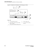
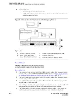
Figure 210: Connections for Telephone Used for Emergency Transfer
TC
TK
LC
ST
1M
1m
2M
2m
3M
ALARM MONITORS
EM TRANS RELAY PWR
ACC PWR
3m
3w
TC
TK
LC
ST
TC
TK
LC
ST
TC
TK
LC
ST
TC
TK
LC
ST
C
O
M
1
N
O
1
N
C
2
N
C
1
C
O
M
2
N
O
2
C
O
M
3
N
C
3
G
R
D
-48
V
1
2
3
2822
25
50
1
EMXR
2822
r758580b MMR 042996
Figure notes
1
To Network Interface Circuitry
2
To TN747B (or Equivalent) Central Office
Trunk Circuit Pack
3
To Blue or White Station Distribution Field
4
To Power Transfer Unit
5
To Control Carrier Auxiliary
Connector


