Install and Wire Telephones
Task List: Typical Emergency Transfer Panel and Telephone Installation
SI Installation and Upgrades
545
June 2004
Figure 215: Example Adjunct Power Connections
Return to Task List
Install the Queue Warning Indicator
Return to Task List
The connections for the queue warning indicator are the same as external ringing. An AC indicator
(lamp) such as a 21C49 can be used in a Uniform Call Distribution/Direct Departmental Calling
(UCD/DDC) queue.
The lamp is connected to an information outlet. The system side of the MDF is connected to an analog
line circuit pack located in a port carrier.
1
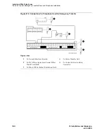
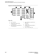
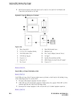
Wire the queue warning indicator to the information outlet as shown in
Figure 216, 3-Pair and 4-
Pair Modularity,
on page 546 and
Figure 217, Example Adjunct Power Connections,
on page 547.
2
Administer using the Administrator’s Guide for Avaya Communication Manager (555-233-506).
Figure notes
1
Typical Display Telephone
2
Individual Power Supply (Such as
1151A1 or 1151A2)
3
Information Outlet (Modular Jack)
4
4-Pair D-Inside Wire (DIW) Cable
5
Satellite Site or Adapter Location
6
25-Pair D-Inside Wire (DIW) Cable
7
Station Side of Main Distribution
Frame (MDF)
8
100P6A Patch Cord or Jumpers
9
System Side of Main Distribution
Frame (MDF)
10
25-Pair Cable to System Cabinet
(Analog Line Circuit Pack)
11
Equipment Room
12
Satellite Location
13
Work Location
14
Bulk Power Supply (Such as 1145B)
cydfadjn KLC 020599
1
2
3
4
5
6
7
8
9
10
11
12
13
14
14


