Add IP Solutions
Task list: Install the TN802B in IP Trunk mode
SI Installation and Upgrades
627
June 2004
15
Check Network Services
on page 641
16
Test the External Connection to the LAN
on page 625
17
Test the IP Interface Onboard LAN Connections
on page 642
Prepare for Installation
Return to Task List
Have the following equipment on site before your shipment arrives:
•
AC power outlets for the modem and monitor.
•
Three unoccupied and adjoining port slots in the DEFINITY ECS for the TN802B IP Interface, if
needed.
•
The TN802B occupies only one slot, but it needs the two slots to its left for clearance.
•
A 10 BaseT or 10/100 BaseT Ethernet connection into your local area network for the TN802B.
•
One or more valid, unused IP addresses on your network that can be assigned to the IP Interface
server. You also need the subnet mask and default gateway.
•
An analog telephone line reserved (DID is okay) for the IP Interface diagnostic modem
•
A valid telephone number reserved for the IP Interface diagnostic modem
In addition if non-U.S. customer:
•
Modem comparable to a U.S. Robotics Sportster Model USR 33.6 EXT.
•
Cable from modem to TN802B external cable assembly.
We recommend that you protect your cabinet with an uninterruptible power system (UPS).
Return to Task List
Check your Shipment
Return to Task List
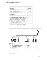
When your DEFINITY IP Interface Assembly order arrives at your site, check the contents (see
Required
Hardware on page 617
).
1
Inspect the shipping carton for damage before opening it. If the box is damaged, do not open it.
Inform the shipping company, and ask for instructions on filing a claim.
2
If the box is undamaged, check the contents against the packing slip. Check the condition of each
component, and note any damage or shortages on the packing slip. See
Required Hardware on
page 617
for what the carton should contain for each IP Interface ordered.
3
Read and follow any directions inserted into the package by the factory.
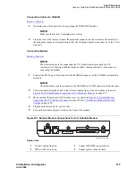
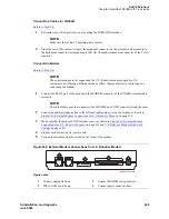
The TN802B external cable assembly is a bundle of cables with an amphenol connector at the end of the
bundle and various PC-type connectors (VGA, Universal Serial Bus [USB], mouse, keyboard, Ethernet,
modem, and COM2) at the ends of the individual cables. See
Figure 240, TN802B IP Interface External
Cable Assembly,
on page 618. Look for the label where the bundle enters the amphenol connector.


