Install and Administer Trunks
Add TN1654 DS1 Converter (r only)
SI Installation and Upgrades
685
June 2004
Connecting Through a Channel Service Unit
Return to Task List
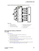
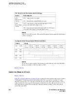
Figure 278, DS1 Converter Connections for T1 Service — Part 2,
on page 686 shows a typical
connection for a T1 line, and
Figure 279, DS1 Converter Connections for 120-ohm E1 Service — Part 2,
on page 687 shows a typical connection for an E1 line.
1
Connect the H600-348 Quad Cable to the DTE jacks on each of the 4 CSUs.
2
You may need an adapter cable to connect the H600-348 cable to the CSU (see
Adapter
Descriptions
on page 687).
3
Connect one end of the H600-383 cable to the network jack on the CSU and the other end to the
smart jack.
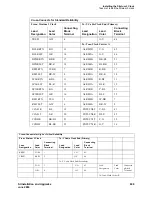
Connection to the remote-located system is the same as that shown in
Figure 280, DS1 Converter Circuit
Pack Switches,
on page 688 and
Figure 281, CAMA Numbering Format form,
on page 688.
Y Cable Lengths
on page 689 shows theY cable lengths.
The distinction between facility types is important when using TN1654 circuit packs. The facility used to
carry control channel messages between the pair of DS1 converter circuit packs and all packet traffic is
known as the primary facility. The facility used to backup and takeover for the primary facility in the
event of primary facility failure is known as the secondary facility. The TN1654 allows either facility, A
or B, to be a primary channel. The control channel is restricted to only the A or B facilities. This permits
full 24-channel access (T1) or 31-channel access (E1) for facilities C and D to support user traffic.


