Installing the Stratum 3 Clock
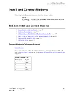
Task List: Install the Stratum 3 clock
696
SI Installation and Upgrades
June 2004
NOTE:
Only SW 1 and SW2 are used. SW1 controls the output of alarm signals from the Stratum
3 Clock circuit pack.
NOTE:
Set switches 1 and 2 according to the distance from the Stratum 3 clock to the DEFINITY
System. Set switch 3 to ON. Set switch 4 to OFF.
Return to Task List
Cable the Stratum 3 Clock
Return to Task List
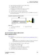
Figure 283, Typical Connections to Stratum 3 Clock,
on page 697 shows typical connections to a Stratum
3 Clock cabinet. Connections are made through the yellow field cross-connect. A custom “Y” cable
(H600-274) connects the CSU to the DS1 circuit pack and taps off the input for the Stratum 3 Clock. A
resistor built into the cable to provides the necessary isolation between the system and the clock. The “Y”
cable plugs directly into the CSU and connects to standard cables for interface to the system and the
yellow field on the MDF.
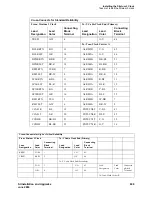
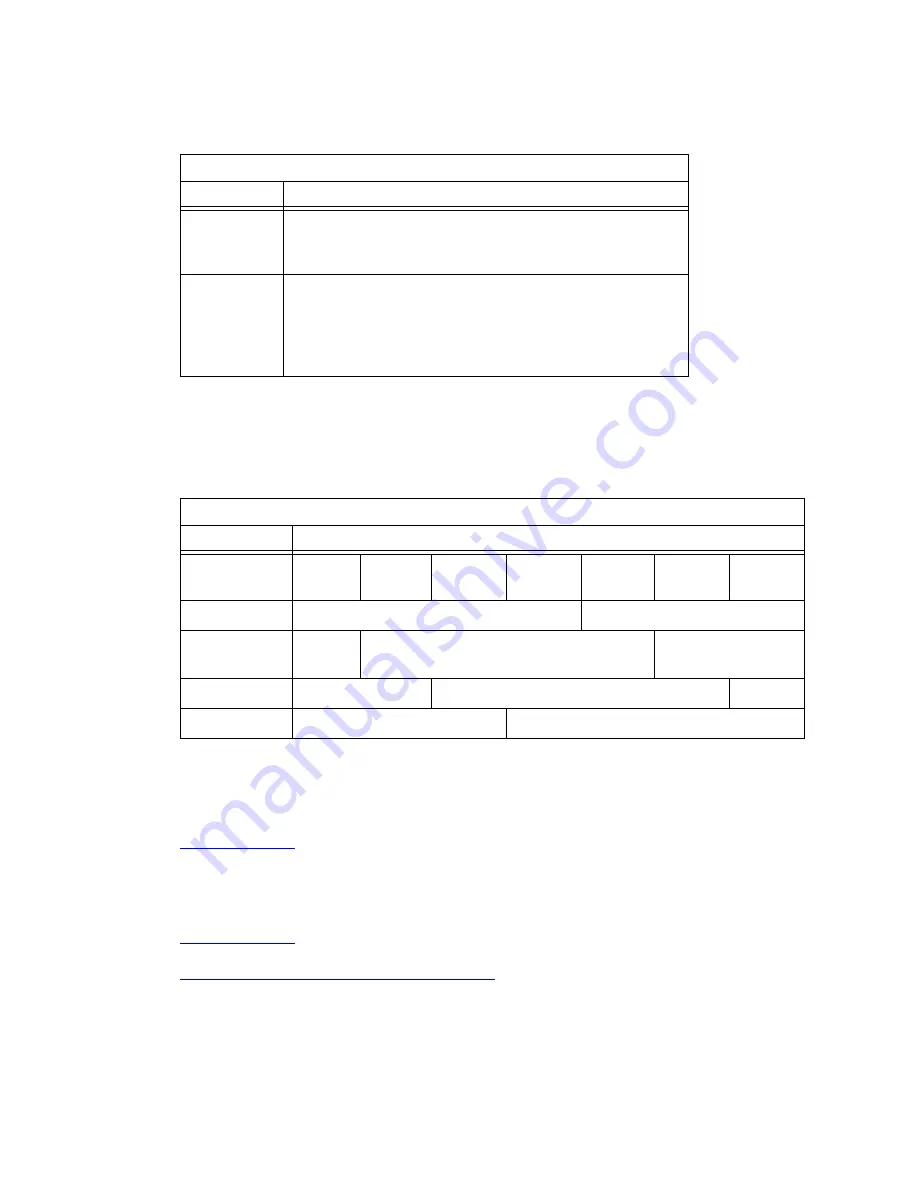
ST3 Clock Circuit Pack Option Switch Settings
Switch
Status/Results
SW1
Minor Alarm
Control
OFF = minor alarm never output
ON = minor alarm is output if holdover occurs
SW2
Major Alarm
Control
OFF = major alarm is output and fail lamp lights if 5 VDC
power is lost and 4 kHz output is lost
ON = major alarm is output and fail lamp lights if 5 VDC power
is lost and 4 kHz output is lost and holdover occurs
Composite Clock Timing Output (TOCA) Circuit Pack
Switch
Range
500
1000
1 ft
(0.3 m)
500 ft
(152 m)
1000 ft
(305 m)
1500 ft
(457 m)
2000 ft
(610 m)
2500 ft
(762 m)
3000 ft
(914 m)
OFF
OFF
<-------------------------------------------------->
ON
OFF
<----------------------------------------------------
>
OFF
ON
<---------------------------------------------------->
ON
ON
<--------------------------------------------------->


