Adjuncts and Peripherals
909A/B universal coupler
832
SI Installation and Upgrades
June 2004
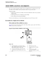
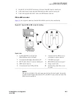
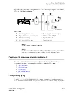
Figure 324: Typical 909A/B universal coupler
The 909A is the direct current (DC) version of the coupler, and cabinet power supplies -48 VDC power.
The 909B is the alternating current (AC) version, and power is supplied from a separate power supply
(such as the KS-22911L2).
The DIP switches on the unit set:
•
Protection/Paging selection
—
For AUX trunk paging and malicious call trace, set to C2. Set the
switch to C1 for all other applications.
•
Output attenuation (-9 or -15 dBm)
—
Setting depends on output level of music source.
•
Output impedance (8 ohms, 1.5 k
Ω
, and 50 k
Ω
)
—
This switch only requires setting if the
Protection/Paging switch is set to C2 and the coupler is supplying background music to a
customer-supplied paging amplifier.
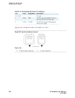
The pinouts for J1, J2, and J3 are provided in
Table 45
,
Table 46
, and
Table 47
. Refer to these tables when
connecting music or paging equipment.
Figure notes
1
909A/B universal coupler
2
J1 8-pin modular jack
3
J2 8-pin modular jack
4
J3 7-pin modular jack
5
DIP switch location
Table 45: J1 Pin Assignments (System Connections) 1 of 2
Pin
Color
Designation
Description
1
White-Orange
—
Not Used
2
Orange
PG2/BZ2
Seizure control lead, connected to -48 VDC from the
system or from the 909A/B when the protection paging
switch is set to C2, or to -48 VDC on the 909A/B when
protection/paging switch is set to C1
1 of 2
909_brkt KLC 042296

