Adjuncts and Peripherals
Paging and announcement equipment
842
SI Installation and Upgrades
June 2004
9
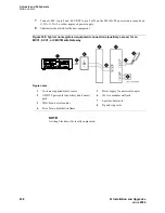
Connect an approved -48 VDC power source to the
-48
and
GRD
terminals (pins 5 and 2,
respectively, of J3).
10
Administer the switch for the new equipment.
NOTE:
For additional installation information, refer to 909A/909B Universal Coupler Installation
Instructions, which is normally shipped with the 909A/909B Universal Coupler.
ESPA radio paging
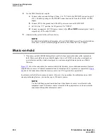
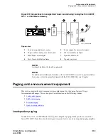
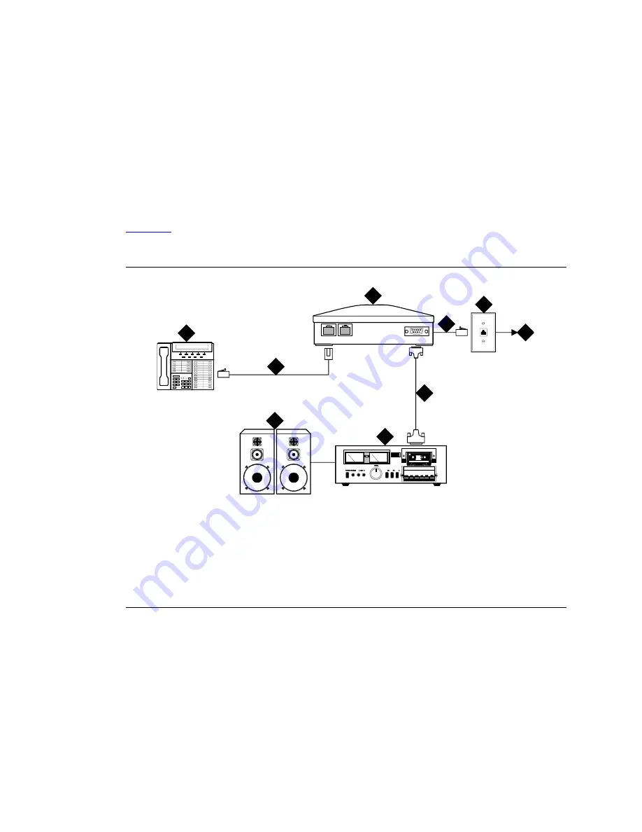
Figure 331
shows typical connections to European Standard Paging Access (ESPA) equipment. Connect
the LINE jack on the PassageWay interface to a digital line 4-wire DCP circuit pack through the MDF.
Figure 331: Typical ESPA radio paging connections
External ringing
Connections for external ringing are at an information outlet. The system side of the main distribution
frame (MDF) is connected to a TN2183 (or equivalent) analog line circuit pack in an MCC1, SCC1, or
CMC1 Media Gateway.
NOTE:
Up to three devices can be connected to one analog line circuit pack port.
Figure notes
1
DCP telephone
2
4-pair modular cord
3
PassageWay interface
4
4-pair modular cord
5
103A or modular wall jack
6
To digital line circuit pack
7
RS-232 connector
8
ESPA radio paging
equipment
9
Loudspeaker paging system
cydf004 RPY 123097
PHONE
LINE
POWER
1
2
3
4
5
6
7
8
9

