Electrical Installation
16
Avaya
t
RS9 UPS (9–18 kVA, 9-Slot Models) Site Preparation, Installation and Operator’s Manual
S
164201543 Rev A
7.
See Figure 12 on page 18 for the output wiring diagram. Make
UPS output connections on the backplane board terminating
studs. Compression lugs (supplied in the accessory kit) may be
installed on the proper terminating studs. Wires may also be
terminated with ring terminals, which are attached to the
output terminating studs.
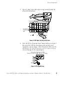
Figure 10 shows output wiring configurations for various
output voltages. You must also set the operating menu
parameter 4-2-4 for the required output voltage.
NOTE
For Avaya RS9 UPS models with low-voltage hardwire output, it
is recommended to divide the total load as equally as possible between X1 and X2, as
shown in Figure 10.
NOTE
Failure to balance the loads may cause an overload alarm even if the full
capacity of the UPS has not been reached.
N/-DC
100/200, 110/220, 127/220, 120/208, or 120/240V Out
Parameter 4-2-4 set to 200, 220, 208, or 240, as required.
X2
X1
X
X
N
L1
X
L2
100, 110, 127, or 120
50%
100, 110, 127, or 120
50%
X1
X2
200, 220
208, or 240
Figure 10. Split-Phase Output Connections


