EXP-INTF (Expansion Interface Circuit Pack)
Issue 1 May 2002
8-765
555-233-143
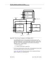
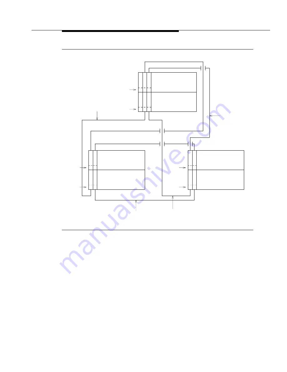
Figure 8-35.
Direct Connect Configuration with Duplicated PNC
In a duplicated PNC there is an A-side and a B-side PNC. Every EI in this
diagram is labeled with an A or a B designating to which PNC it belongs. Note
that a PNC’s designation (A or B) does not relate directly to the carrier where its
EIS reside. Again, only one of an PN’s EIs can function as the Archangel
(TDM-bus master). An PN’s EI that is:
■
On the active PNC
■
Logically connected to the media server
is the only one that can function in this mode. In normal operation, its amber LED
should be blinking at a rate of 2 seconds on and 200 ms off.
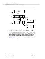
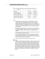
shows the location of EIs in a typical center stage
switch configuration with unduplicated PNC.
PPN
CAB 1
CARRIER D
CARRIER C
EPN
CAB 2
CARRIER B
CARRIER A
EPN
CAB 3
CARRIER B
CARRIER A
FIBER 1 (A)
FIBER 1 (B)
FIBER 2 (A)
FIBER 2 (B)
FIBER 3 (B)
FIBER 3 (A)
E
E
E E
E
E
E E
E
E
E E
I
I
I I
3
2
3
2
Slot #
Slot #
Slot #
2
1
2
1
2
1
2
1
Slot #
Slot #
Slot #
I
I
I I
I
I
I I
(A) (A)
(A) (A)
(A) (A)
(B)
(B)
(B)
(B)
(B) (B)
Summary of Contents for S8700 Series
Page 50: ...Maintenance Architecture 555 233 143 1 26 Issue 1 May 2002 ...
Page 74: ...Initialization and Recovery 555 233 143 3 12 Issue 1 May 2002 ...
Page 186: ...Alarms Errors and Troubleshooting 555 233 143 4 112 Issue 1 May 2002 ...
Page 232: ...Additional Maintenance Procedures 555 233 143 5 46 Issue 1 May 2002 ...
Page 635: ...status psa Issue 1 May 2002 7 379 555 233 143 status psa See status tti on page 7 406 ...
Page 722: ...Maintenance Commands 555 233 143 7 466 Issue 1 May 2002 ...


