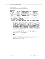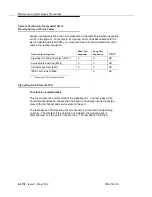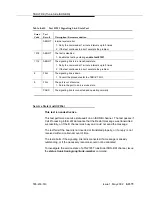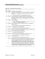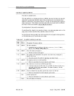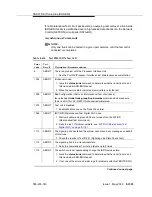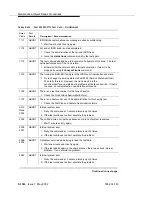
TDM-BUS (TDM Bus)
Issue 1 May 2002
8-1591
555-233-143
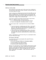
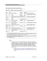
If the TDM bus problem is present when the circuit pack is inserted, but is
resolved when the circuit pack is removed, either the circuit pack or the backplane
pins in that slot are causing the problem. If the backplane pins are intact, replace
the circuit pack. If some of the tests fail regardless of whether the circuit pack is
inserted or removed, and the backplane pins are intact, the circuit pack is not the
cause of the problem. In a multiple failure situation, the circuit pack could be one
cause of the TDM bus problem. However, other simultaneous failures might also
be responsible for TDM-bus faults.
In Procedure 2, an option of working either with one circuit pack at a time or with
multiple circuit packs simultaneously is available. In view of this capability,
determine the level of service interruption that will be acceptable during the
procedure. If causing a disruption to all users in the port network is deemed
permissible, large groups of circuit packs should be worked with in order to get the
job done quickly. However, if large service disruptions are to be avoided, work
with one circuit pack at a time. This option is slower, but it disrupts only the users
of a single circuit pack.
1. Remove one or several circuit packs as appropriate. Any circuit packs that
reside on the TDM bus that have been recently inserted should be checked
first.
If you decide to remove multiple circuit packs, consider working with an
entire carrier at a time to more quickly and reliably determine which circuit
packs are not the source of trouble.
2. Run test tdm P to determine whether the TDM-bus fault is still present.
3. If any of the TDM-bus tests fail:
■
Determine whether the backplane pins in the removed circuit pack’s
slot appear to be bent.
■
If the backplane pins are not bent, reinsert the circuit pack(s), and
perform Procedure 2 for the next set of circuit packs.
■
If the backplane pins are bent, remove power to this carrier in the
manner described previously.
■
Straighten or replace the pins and reinsert the circuit pack.
■
Restore power and repeat Procedure 2, beginning with Step 2, for
the same circuit pack(s).
4. If none of the TDM-bus tests fail:
■
Reinsert the circuit pack(s) one at a time, and repeat the following
substeps until every circuit pack has been reinserted.
■
Run test tdm P to determine whether the TDM-bus fault has
returned.
■
If any of the TDM-bus tests fail, the reinserted circuit pack is
defective. Replace this circuit pack and repeat this procedure for
the next circuit pack.
■
If none of the TDM-bus tests fail when every circuit pack has been
reinserted, the problem has been fixed and the procedure is
completed.
Summary of Contents for S8700 Series
Page 50: ...Maintenance Architecture 555 233 143 1 26 Issue 1 May 2002 ...
Page 74: ...Initialization and Recovery 555 233 143 3 12 Issue 1 May 2002 ...
Page 186: ...Alarms Errors and Troubleshooting 555 233 143 4 112 Issue 1 May 2002 ...
Page 232: ...Additional Maintenance Procedures 555 233 143 5 46 Issue 1 May 2002 ...
Page 635: ...status psa Issue 1 May 2002 7 379 555 233 143 status psa See status tti on page 7 406 ...
Page 722: ...Maintenance Commands 555 233 143 7 466 Issue 1 May 2002 ...

