Issue 1 May 2002
6-1
555-233-143
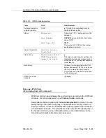
LED Interpretation
This chapter describes the meanings of the LEDs on system components and the
alarm levels they indicate. The chapter includes the following topics:
■
■
‘‘Terminal Alarm Notification’’
■
■
■
‘‘Expansion Interface Circuit Pack LEDs’’
■
‘‘Maintenance Circuit Pack LEDs’’
■
‘‘Switch Node Interface LEDs’’
■
‘‘DS1 CONV (TN574/TN1654) Circuit Pack LEDs’’
■
‘‘Tone-Clock Circuit Pack LEDs’’
■
■
■
‘‘Duplication Memory Card LEDs’’
For information on interpreting LEDs and testing procedures during installation,
refer to Installing the Avaya S8700 Media Server for Multi-Connect
Configurations.
Summary of Contents for S8700 Series
Page 50: ...Maintenance Architecture 555 233 143 1 26 Issue 1 May 2002 ...
Page 74: ...Initialization and Recovery 555 233 143 3 12 Issue 1 May 2002 ...
Page 186: ...Alarms Errors and Troubleshooting 555 233 143 4 112 Issue 1 May 2002 ...
Page 232: ...Additional Maintenance Procedures 555 233 143 5 46 Issue 1 May 2002 ...
Page 635: ...status psa Issue 1 May 2002 7 379 555 233 143 status psa See status tti on page 7 406 ...
Page 722: ...Maintenance Commands 555 233 143 7 466 Issue 1 May 2002 ...


