Maintenance-Object Repair Procedures
555-233-143
8-1716
Issue 1 May 2002
TN464 circuit packs support the following:
■
Digital Tie, CO, and DID trunks
■
DS1 off-premises (OPS) lines
■
Narrowband and wideband access endpoint ports
■
ISDN-PRI trunks and accompanying signaling channel
■
PRI endpoint ports (PE-BCHL) and accompanying signaling channel
The TN464 supports digital Tie, CO, and DID trunks, and OPS lines. On-board
firmware performs call control signaling for the Tie, CO and DID trunks and OPS
lines. ISDN-PRI trunk and PRI-endpoint signaling (Q.921, Q.931) is received and
generated by system software and is transmitted on a system link through the
TN1655 Packet Interface and packet bus to the UDS1 where it is placed on the
D channel. Signaling over the DS1 link has to be synchronized between the
transmitting and receiving ends to ensure error-free communication. See
(Port-Network Synchronization)’’ on page 8-1509
in this MO for details.
Each trunk, line, or endpoint has its own maintenance strategy, but all depend on
the health of the UDS1 Interface circuit pack. See the following MOs for details:
,
,
‘‘OPS-LINE (DS1 Off-Premises Station Line)’’
‘‘ISDN-LNK (ISDN-PRI Signaling Link Port)’’
,
‘‘WAE-PORT (Wideband Access Endpoint Port)’’
and
‘‘PE-BCHL (PRI Endpoint Port)’’
. The maintenance strategy for the TN464
UDS1 Interface circuit pack (UDS1-BD) is very similar to the maintenance
strategy for the TN767 DS1 Interface circuit pack (DS1-BD). The same
commands are used for administering and testing the boards. The differences in
maintenance strategy between the boards result from the UDS1 circuit pack’s
direct interface to the Packet bus used for ISDN-PRI signaling (ISDN-LNK). While
both the TN464 and TN767 can support ISDN-PRI B channels, ISDN-PRI
D-channel signaling applications require a TN464 UDS1 circuit pack.
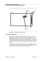
The UDS1 circuit pack, combined with the 120A1 CSU module forms an
Enhanced Integrated CSU. The 120A1 CSU module, when combined with the
functionality provided by the TN464F hardware and firmware, and switch
software, provides functionality equivalent to an external stand-alone ESF T1
CSU. The 120A1 CSU module connects to the UDS1 circuit pack on the I/O
connector panel behind the port carrier. The CSU module thus becomes an
integrated part of the S8700 Multi-Connect system. Throughout this MO, the term
120A1 will mean a 120A1 or later suffix CSU module.
The Enhanced Integrated CSU is for use in the United States of America with
1.544-Mbps DS1 service. For further details on the 120A1 CSU module refer to
DEFINITY Communications System Generic 1, Generic 2, and Generic 3 V1 and
V2 - Integrated CSU Module Installation and Operation.
Summary of Contents for S8700 Series
Page 50: ...Maintenance Architecture 555 233 143 1 26 Issue 1 May 2002 ...
Page 74: ...Initialization and Recovery 555 233 143 3 12 Issue 1 May 2002 ...
Page 186: ...Alarms Errors and Troubleshooting 555 233 143 4 112 Issue 1 May 2002 ...
Page 232: ...Additional Maintenance Procedures 555 233 143 5 46 Issue 1 May 2002 ...
Page 635: ...status psa Issue 1 May 2002 7 379 555 233 143 status psa See status tti on page 7 406 ...
Page 722: ...Maintenance Commands 555 233 143 7 466 Issue 1 May 2002 ...

