Maintenance Commands
555-233-143
7-62
Issue 1 May 2002
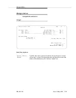
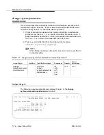
Output
The following fields appear on page 2 when a DS1 CONV complex is
administered on the fiber link. Only the DS1 CONV complex attributes are
administered here. The circuit pack itself is administered by change circuit
pack. Entries on page 2 represent the A-PNC. If the PNC is duplicated, these
fields are repeated on page 3 for the B-PNC. Page 3 has display-only fields that
can be changed only by changing their counterpoints on page 2.
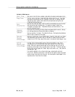
Fiber Link #
This display-only field shows the identifying number of the fiber link
entered on the command line.
Board Location
The physical address (cabinet-carrier-slot) of the circuit packs comprising
the two endpoints (ENDPOINT-1 and ENDPOINT-2) of the fiber link.
Board Type
This display-only field shows the type of circuit pack administered at each
endpoint (“ei” or “sni”).
DS1 Converter?
y indicates that a DS1C converter complex is used on this link to remotely
locate a port network. If this is the case, a second page displays for
administration of the DS1C complex attributes.
Fiber
Translation
Enter multi-mode or single-mode. This field is used for faster remote
diagnosis.
Converter
Enter y or n. This field is used for faster remote diagnosis.
Type of
Transceivers
Enter A or B. This field is used for faster remote diagnosis.
Converter Type
Enter Avaya or other. Appears when the converter field on the Fiber Link
Administration screen is set to y.
Board Location
This field under the heading DS1C-1 is used to define the physical
location of the converter board connected to ENDPOINT-1. It is a data
entry field consisting of the board’s physical address by
cabinet-carrier-slot. When the location is entered, validation is performed
to ensure that the board has been administered and is of the correct type
(DS1 CONV).
DS1 Converter
Facilities
The fields under this heading define attributes of the four DS1 facilities (A,
B, C, D) that can be connected to the DS1 CONV.
Facility
Installed?
This specifies (y or n) whether the indicated facility has been provided and
installed. Facility A is required for the DS1 CONV complex.
Summary of Contents for S8700 Series
Page 50: ...Maintenance Architecture 555 233 143 1 26 Issue 1 May 2002 ...
Page 74: ...Initialization and Recovery 555 233 143 3 12 Issue 1 May 2002 ...
Page 186: ...Alarms Errors and Troubleshooting 555 233 143 4 112 Issue 1 May 2002 ...
Page 232: ...Additional Maintenance Procedures 555 233 143 5 46 Issue 1 May 2002 ...
Page 635: ...status psa Issue 1 May 2002 7 379 555 233 143 status psa See status tti on page 7 406 ...
Page 722: ...Maintenance Commands 555 233 143 7 466 Issue 1 May 2002 ...


