Maintenance-Object Repair Procedures
555-233-143
8-666
Issue 1 May 2002
DS1 CONV-1 and DS1 CONV-2 Line
Compensation
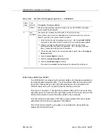
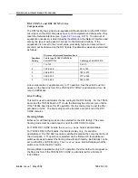
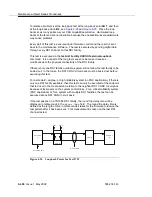
The DS1 facility line signal is pre-equalized at the transmitter on the DS1 CONV
circuit pack so that DS1 line pulses have correct amplitude and shape when they
reach the Network Interface (see
). The amount of
equalization necessary is determined by the distance to the Network Interface and
also by the type of wiring used to connect to the Network Interface. If the
equalization is not set to the correct value, potentially high error rates (errored
seconds) will be observed on the DS1 facility. Equalization values are determined
as follows:
Line compensation is applicable only to T1 operation, thus these fields will not
appear on the fiber-link form if the TN1654 DS1 CONV is administered for a bit
rate of 2.048 Mbps.
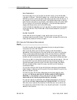
Line Coding
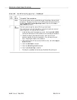
This field is used to administer the line coding for the DS1 facility. For the TN574
board and the TN1654 board in T1 mode, the field may be set to ami-zcs or b8zs.
If the TN1654 board is set for E1 operation, the line coding may be set to either
ami-basic or hdb3. The line coding must be the same at each end of the DS1
CONV complex.
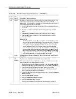
Framing Mode
Either esf or d4 framing mode can be selected for the DS1 facility. The same
framing mode must be used at each end of the DS1 CONV complex.
For TN574 DS1 CONV boards, the
Framing Mode
field is administrable.
For TN1654 DS1 CONV boards, this field is display only. It cannot be
administered. The TN1654 has option switches located on the component side of
the circuit pack. If T1 operation is selected via the first switch, four additional
switches are used to select the framing mode for each facility. Each facility can be
set to either D4 or ESF framing. The
Framing Mode
field will display what the
switch is set to for the DS1 facility.
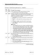
Framing Mode is applicable only to T1 operation, thus this field will not appear on
the fiber-link form if the TN1654 DS1 CONV is administered for a bit rate of
2.048 Mbps.
Equalizer
Setting
Distance to Network Interface (feet)
Cable type 22 AWG ABAM &
24 AWG PDS
Cable type 26 AWG PDS
1
1 to 133
0 to 90
2
133 to 266
90 to 180
3
266 to 399
180 to 270
4
399 to 533
270 to 360
5
533 to 655
360 to 450
Summary of Contents for S8700 Series
Page 50: ...Maintenance Architecture 555 233 143 1 26 Issue 1 May 2002 ...
Page 74: ...Initialization and Recovery 555 233 143 3 12 Issue 1 May 2002 ...
Page 186: ...Alarms Errors and Troubleshooting 555 233 143 4 112 Issue 1 May 2002 ...
Page 232: ...Additional Maintenance Procedures 555 233 143 5 46 Issue 1 May 2002 ...
Page 635: ...status psa Issue 1 May 2002 7 379 555 233 143 status psa See status tti on page 7 406 ...
Page 722: ...Maintenance Commands 555 233 143 7 466 Issue 1 May 2002 ...

