Maintenance-Object Repair Procedures
555-233-143
8-1718
Issue 1 May 2002
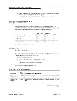
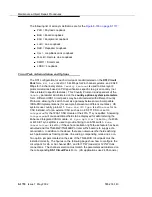
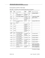
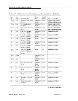
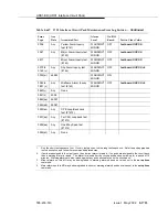
The following list of acronym definitions are for the
■
PLB = Payload Loopback
■
BLB = Board Loopback
■
ELB = Equipment Loopback
■
LLB = Line Loopback
■
RLB = Repeater Loopback
■
CLJ = Loop-Back Jack Loopback
■
R-LLB = Remote Line Loopback
■
SMRT = Smart Jack
■
LPBK = Loopback
Circuit Pack Administration and Options
The DS1 configuration for each circuit pack is administered on the DS1 Circuit
Pack form.
Bit Rate
is set to 1.544 Mbps for 24-channel systems, and 2.048
Mbps for 32-channel systems.
Country Protocol
is used to drive layer-3
protocol decisions based on PRI specifications specific to a given country (not
those related to specific features). This Country Protocol is independent of the
Country
parameter administered on the country-options system-parameters
form. Different UDS1 circuit packs may be administered with different Country
Protocols, allowing the switch to act as a gateway between two incompatible
ISDN-PRI implementations (for example, between two different countries). US
systems use country protocol 1.
Near-End CSU Type
is set to
other
for no
CSU installed or for an external CSU such as an ESF T1 CSU, or set to
integrated
for the 120A1 CSU module or the 401A T1 sync splitter. Answering
integrated
will cause additional fields to be displayed for administering the
Enhanced Integrated CSU module.
E1 Sync-Splitter?
is set to
y
if a 402A
or 403A E1 sync splitter is used to provide timing to an ATM switch.
Echo
Cancellation?
is set to
y
if the echo cancellation right-to-use feature has been
activated and this TN464GP/TN2464BP or later suffix board is to supply echo
cancellation. In addition to the above there are numerous other fields defining
such parameters as framing modes, line coding, companding mode and so on.
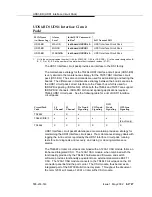
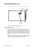
Two option jumpers located on the side of the TN464C/D circuit pack must be
installed correctly. The figures on the following page show how to configure the
circuit pack for 24- or 32-channel DS1, and for 75*W (coaxial) or 120*W trunk
connections. The channel selection must match the parameters administered on
the corresponding DS1 Circuit Pack Form. (US applications use 24 Channels.)
Summary of Contents for S8700 Series
Page 50: ...Maintenance Architecture 555 233 143 1 26 Issue 1 May 2002 ...
Page 74: ...Initialization and Recovery 555 233 143 3 12 Issue 1 May 2002 ...
Page 186: ...Alarms Errors and Troubleshooting 555 233 143 4 112 Issue 1 May 2002 ...
Page 232: ...Additional Maintenance Procedures 555 233 143 5 46 Issue 1 May 2002 ...
Page 635: ...status psa Issue 1 May 2002 7 379 555 233 143 status psa See status tti on page 7 406 ...
Page 722: ...Maintenance Commands 555 233 143 7 466 Issue 1 May 2002 ...

