
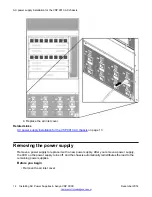
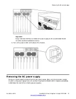

The individual on and off power switches and inlet connectors at the back of the Virtual Services
Platform 9010 AC chassis are numbered decreasing from left to right, with 4, 3, 2, and 1 on the first
row, and then 8, 7, 6, and 5 on the second row.
Related Links
on page 15
on page 18
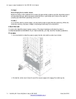
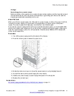
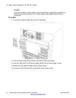
Removing the air inlet cover
Before you can install or remove a power supply or cooling module, you must remove the air inlet
cover from the chassis.
Procedure
1. Grasp the cover on each side.
2. Lift the cover up and away from the chassis.
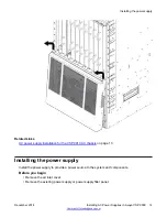
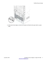
AC power supply installation for the VSP 9010 AC chassis
14
Installing AC Power Supplies in Avaya VSP 9000
December 2014


