

Chapter 5: AC power supply installation for
the VSP 9012 chassis
This chapter describes the procedures to install AC power supplies in the Avaya Virtual Services
Platform 9012 chassis. The Virtual Services Platform 9012 chassis provides six slots for power
supplies.
About this task
• You need qualified service personnel to install and replace Virtual Services Platform 9000
components.
Voltage:
Risk of injury by electric shock
Before working on this equipment, be aware of proper safety practices and the hazards involved
with electrical circuits. Use only power cords that have a grounding path. Ensure the switch is
properly grounded before powering on the unit.
For information about the minimum software version required to support the hardware, see
Release
Notes for Avaya Virtual Services Platform 9000,
NN46250-401.
Important:
Avaya recommends that you install each power supply on its own dedicated branch circuit for
electrical installation reasons.
The following table lists the estimated time to install an AC power supply for the Virtual Services
Platform 9012 chassis. The installation time depends on the number of power supplies you install.
Table 4: Estimated time
Task
Estimated Time
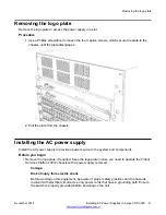
Removing the logo plate
1 minute
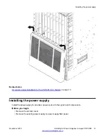
Installing the AC power supply
1 minute
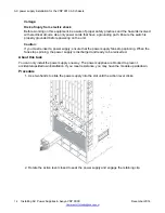
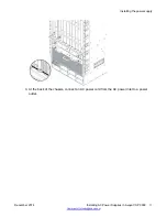
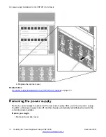
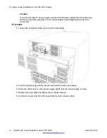
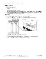
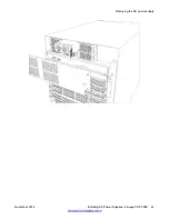
The Virtual Services Platform 9012 chassis ships with no installed power supplies. In the front of the
chassis, power supply slots are numbered increasing from left to right, with 1, 2, and 3 on the first
row, and then 4, 5, and 6 on the second row. Install the first power supply in the top-left slot.
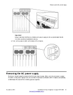
The individual on and off AC power switches and AC IEC60320 inlet connectors at the back of the
Virtual Services Platform 9012 chassis are numbered decreasing from left to right, with 3, 2, and 1
on the first row, and then 6, 5, and 4, on the second row.
20
Installing AC Power Supplies in Avaya VSP 9000
December 2014