
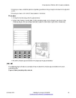
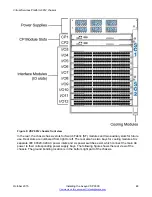

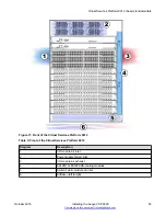
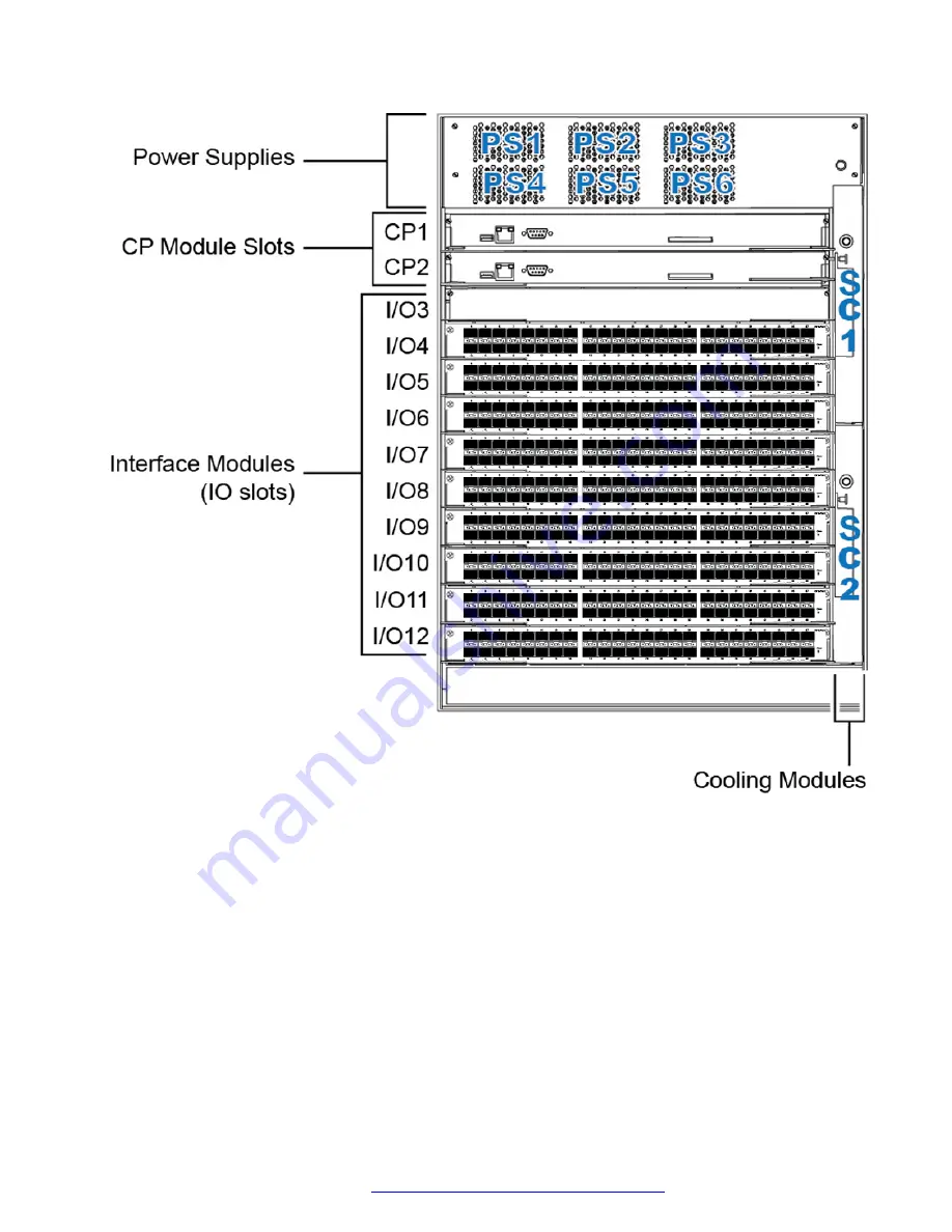
Figure 9: VSP 9012 chassis front view
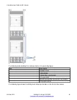
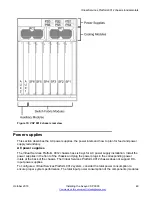
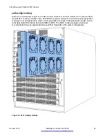
In the rear, the chassis has six slots for Switch Fabric (SF) modules and two auxiliary slots for future
use. Rear slots are numbered from right to left. The rear also has two bays for cooling modules. Six
separate IEC 60320-C20 AC power inlets and six power switches exist, which connect the main AC
power to their corresponding power supply bays. The following figure shows the rear view of the
chassis. The ground bonding location is in the bottom right part of the chassis.
Virtual Services Platform 9012 chassis
October 2015
Installing the Avaya VSP 9000
48


