
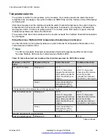
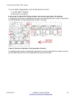
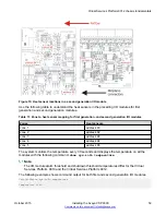
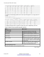
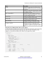
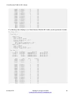
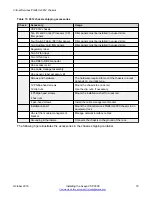
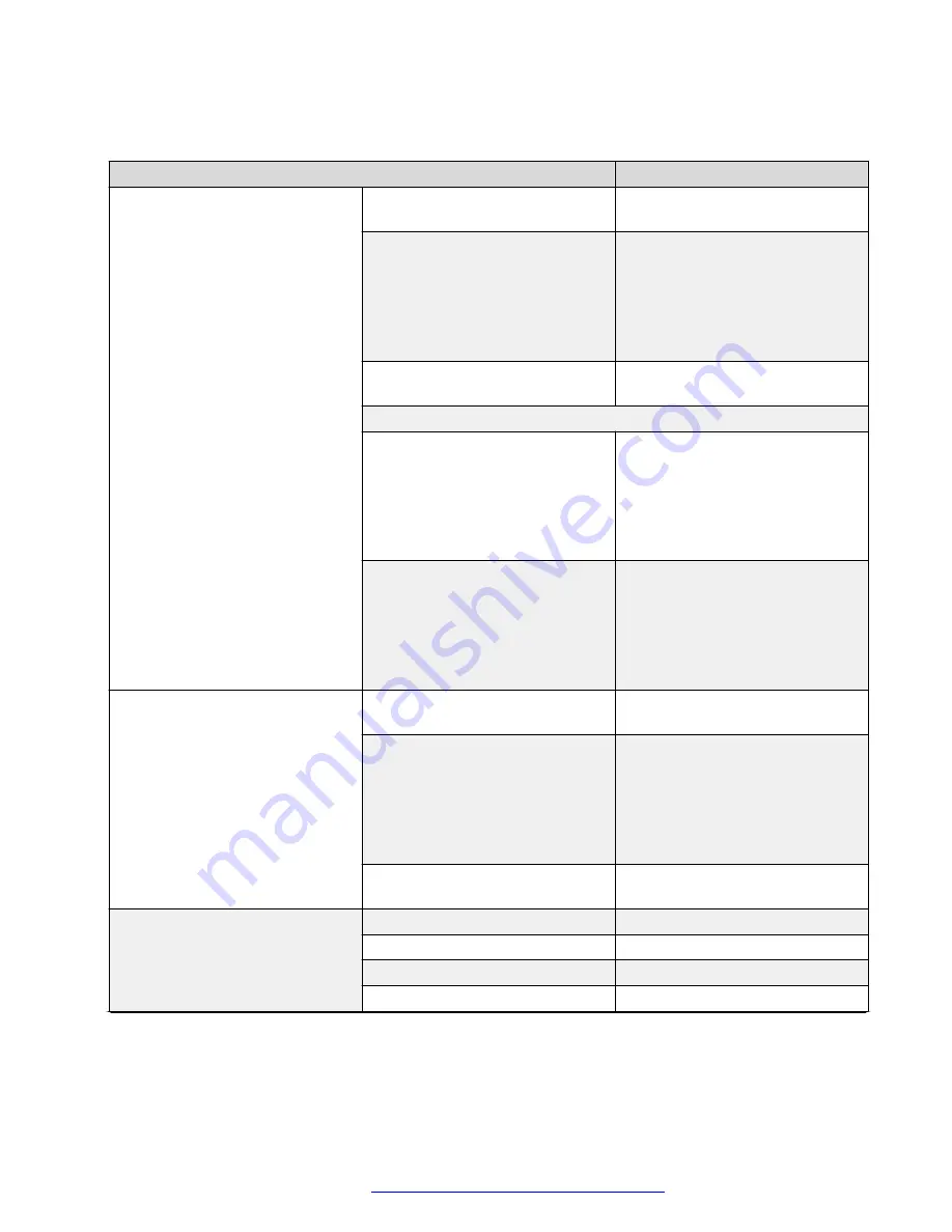
Use the data in the following table to understand the output for the
show sys-info
command on
the Virtual Services Platform 9012.
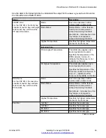
Value
Description
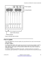
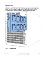
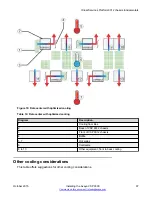
FRONT zone:
For the VSP 9012, the front zone
consists of two fan trays with eight
fans in each tray, which cool the
CP and I/O modules.
Mode:
Each zone operates in either
normal mode or alarm mode.
Mode Status:
Normal Mode – All the fans are
healthy and no temperatures
exceed the warning threshold.
Alarm Mode – Indicates fan or fan
tray failures or temperature
exceed the warning threshold.
Highest Temperature
Specifies the highest temperature
reached in the front zone.
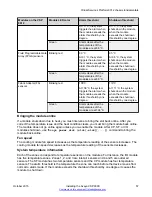
Extended Zone:
FPGA Highest Temperature
This information applies only to
second generation modules.
Specifies the temperature of the
FPGA sensors. A value of --
indicates that this sensor is not
available on this slot.
FA Highest Temperature
This information applies only to
second generation modules.
Specifies the temperature of the
FA sensor, located on the slice. A
value of -- indicates that this
sensor is not available on this slot.
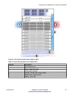
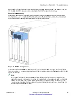
REAR zone:
For the VSP 9012, the rear zone
consists of two fan trays with two
fans in each tray, which cool the
SF modules.
Mode:
Each zone operates in either
normal mode or alarm mode.
Mode Status:
Normal Mode – All the fans are
healthy and no temperatures
exceed the warning threshold.
Alarm Mode – Indicates fan or fan
tray failures or temperature
exceed the warning threshold.
Highest Temperature
Specifies the highest temperature
reached in the front zone.
Fan Info:
IO-FAN 1
Specifies the module type.
IO-FAN 2
Specifies the module type.
SF-FAN 1
Specifies the module type.
SF-FAN 2
Specifies the module type.
Table continues…
Virtual Services Platform 9012 chassis fundamentals
October 2015
Installing the Avaya VSP 9000
63


