
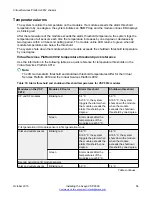
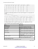
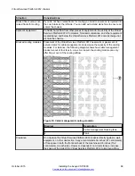
Value
Description
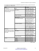
FRONT IO-FAN 1 (1-8)
Specifies the status of each of the
fans in the first cooling module.
FRONT IO-FAN 2 (1-8)
Specifies the status of each of the
fans in the first cooling module.
REAR SF-FAN 1 (1-2)
Specifies the status of each of the
fans in the rear cooling module.
REAR SF-FAN 2 (1-2)
Specifies the status of each of the
fans in the rear cooling module.
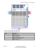
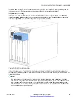
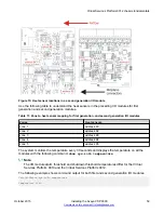
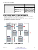
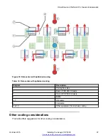
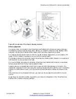
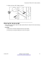
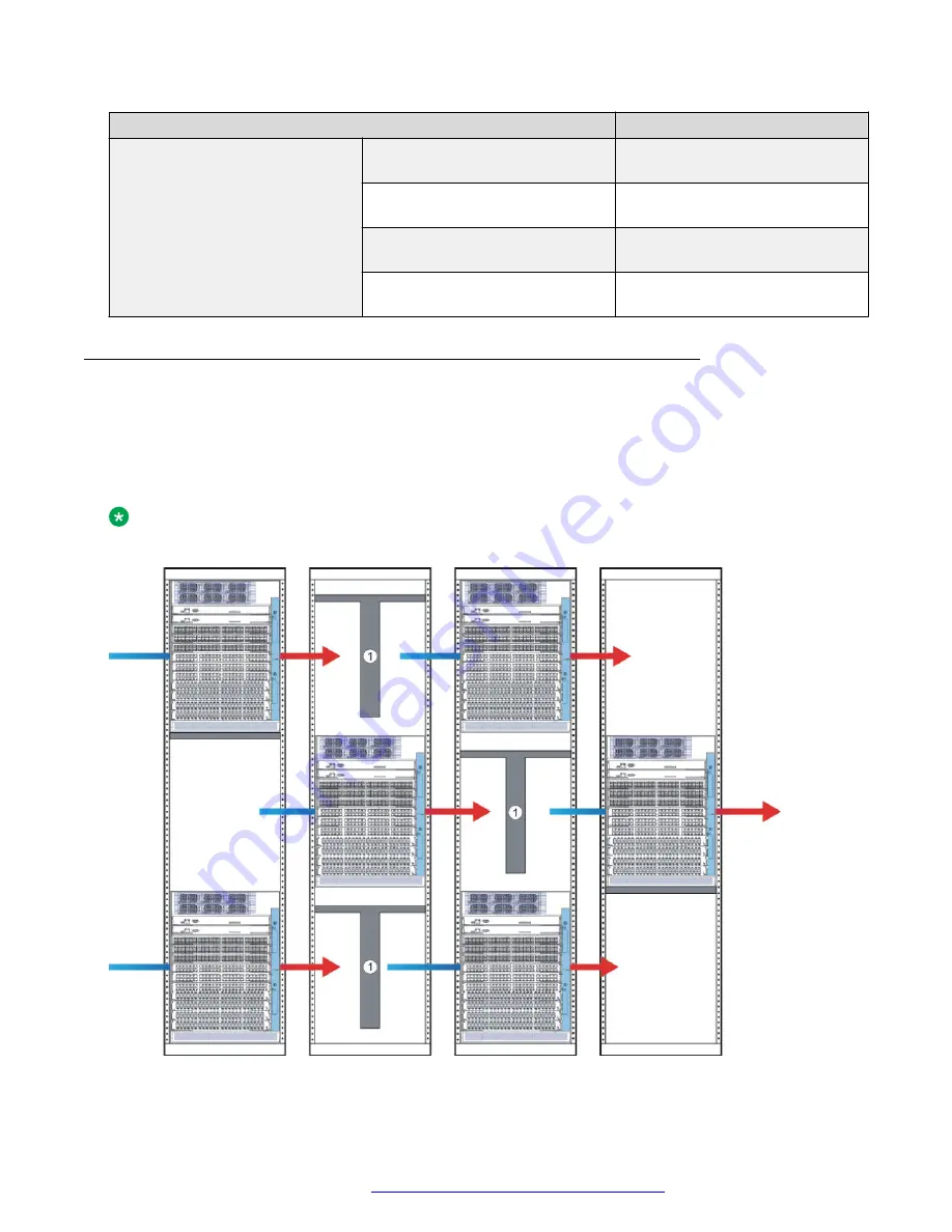
Virtual Services Platform 9012 placement in the rack
If you place each Virtual Services Platform 9012 in a row from left to right, the chassis to the left
discharges hot air into the cool intake of the chassis to the right.
To optimize airflow, stagger each chassis in racks and add a baffle that redirects hot air discharged
by a chassis from the side to the hot aisle at the back.
Note:
Before setting up your data center plan airflow of cool air into each chassis.
Figure 16: Arrangement of VSP 9012 in rack to optimize airflow
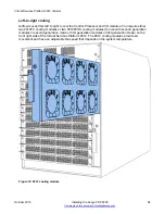
Virtual Services Platform 9012 chassis
October 2015
Installing the Avaya VSP 9000
64


