background image

Figure 3: Job aid

To install the ESD discharge cable, perform this procedure.

1. Connect the ground lug on the ESD discharge cable to a safe and suitable earth ground.

2. Connect all RJ-45 cable connectors to the female RJ-45 connector of the ESD discharge

cable for at least 5 seconds, and then connect each RJ-45 cable connector to the switch.

3. Leave cables connected to the networking equipment. After you connect cables to

networking equipment, the cables do not build up charge.

Technical specifications

The following table provides the technical specifications for the individual switches in this series.
Ensure that the area where you install the switch and where it operates meets these requirements.

Warning:

To avoid bodily injury from hazardous electrical shock and current, never remove the top of the
device. No user-serviceable components are inside.

Table 3: Physical specifications

Specifications

4850GTS

4850GTS-DC

4850GTS-PWR+

Height

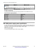
4.4 cm. – 1RU

4.4 cm. – 1RU

4.4 cm. – 1RU

Width

44 cm.

44 cm.

44 cm.

Depth

43.68 cm.

43.68 cm.

43.68 cm.

Weight

11.48 Kg

11.48 Kg

11.98 Kg

MTBF rating

chassis – 311,104 hours

chassis – 311,104 hours

chassis – 214,542
hours

Table continues…

Installing the Avaya VSP 4000 4850GTS Series

May 2016

Installing Avaya Virtual Services Platform 4850GTS Series

20

Comments on this document? infodev@avaya.com

Summary of Contents for VSP 4850 GTS DC

Page 1: ...Installing Avaya Virtual Services Platform 4850GTS Series Release 5 1 NN46251 300 Issue 08 02 May 2016 ...

Page 2: ...Y TO BIND SUCH ENTITY TO THESE TERMS OF USE IF YOU DO NOT HAVE SUCH AUTHORITY OR IF YOU DO NOT WISH TO ACCEPT THESE TERMS OF USE YOU MUST NOT ACCESS OR USE THE HOSTED SERVICE OR AUTHORIZE ANYONE TO ACCESS OR USE THE HOSTED SERVICE Licenses THE SOFTWARE LICENSE TERMS AVAILABLE ON THE AVAYA WEBSITE HTTPS SUPPORT AVAYA COM LICENSEINFO UNDER THE LINK AVAYA SOFTWARE LICENSE TERMS Avaya Products OR SUCH...

Page 3: ...ECT TO CODECS IF THE AVAYA CHANNEL PARTNER IS HOSTING ANY PRODUCTS THAT USE OR EMBED THE G 729 CODEC H 264 CODEC OR H 265 CODEC THE AVAYA CHANNEL PARTNER ACKNOWLEDGES AND AGREES THE AVAYA CHANNEL PARTNER IS RESPONSIBLE FOR ANY AND ALL RELATED FEES AND OR ROYALTIES THE G 729 CODEC IS LICENSED BY SIPRO LAB TELECOM INC SEE WWW SIPRO COM CONTACT HTML THE H 264 AVC CODEC IS LICENSED UNDER THE AVC PATEN...

Page 4: ...e contents 22 Installing the Avaya Virtual Services Platform 4000 on a table or shelf 22 Installing the Avaya Virtual Services Platform 4000 in an equipment rack 24 Cable requirements for the Avaya Virtual Services Platform 4000 26 Installation and removal of Small Form Factor Pluggable SFP transceivers 26 Installing SFP transceivers 26 Removing SFP transceivers 27 RJ 45 connector pin assignments ...

Page 5: ...g Diode LED on the Avaya Virtual Services Platform 4000 36 Front panel LEDs 36 Switch LED state indicators 38 Port LED state indicators 38 Chapter 5 Translations of safety messages 41 Contents May 2016 Installing Avaya Virtual Services Platform 4850GTS Series 5 Comments on this document infodev avaya com ...

Page 6: ...m Viewing Avaya Mentor videos Avaya Mentor videos provide technical content on how to install configure and troubleshoot Avaya products About this task Videos are available on the Avaya Support website listed under the video document type and on the Avaya run channel on YouTube Procedure To find videos on the Avaya Support website go to http support avaya com and perform one of the following actio...

Page 7: ...added to or changed on the Avaya Support website About this task You can subscribe to different types of general notifications for example Product Correction Notices PCN which apply to any product or a specific product You can also subscribe to specific types of documentation for a specific product for example Application Technical Notes for Virtual Services Platform 7000 Procedure 1 In an Interne...

Page 8: ...Scroll through the list and then select the product name 9 Select a release version 10 Select the check box next to the required documentation types Introduction May 2016 Installing Avaya Virtual Services Platform 4850GTS Series 8 Comments on this document infodev avaya com ...

Page 9: ...pecific product and software release to perform searches across an entire document collection For example you can perform a single simultaneous search across the collection to quickly find all occurrences of a particular feature Use this procedure to perform an index search of your documentation collection Before you begin Download the documentation collection zip file to your local computer You m...

Page 10: ... Only Case Sensitive Include Bookmarks Include Comments 6 Click Search The search results show the number of documents and instances found You can sort the search results by Relevance Ranking Date Modified Filename or Location The default is Relevance Ranking Introduction May 2016 Installing Avaya Virtual Services Platform 4850GTS Series 10 Comments on this document infodev avaya com ...

Page 11: ...rvices Platform 4850GTS Series NN46251 300 for VOSS 5 1 Release 5 1 There are no feature related changes for VOSS 5 1 in Installing Avaya Virtual Services Platform 4850GTS Series NN46251 300 May 2016 Installing Avaya Virtual Services Platform 4850GTS Series 11 Comments on this document infodev avaya com ...

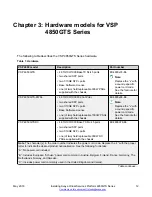
Page 12: ...assis EC4800x88 E6 Note Replace the x with a country specific power cord code See the footnote for details VSP 4850GTS DC 48 10 100 1000 Base TX RJ 45 ports two shared SFP ports two 1 10GE SFP ports one of two field replaceable 300W DC PSUs supplied with the chassis EC4800078 E6 Note The character x in the order number indicates the power cord code Replace the x with the proper letter to indicate ...

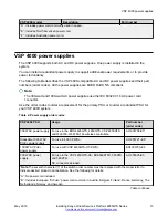
Page 13: ... your VSP 4000 system Table 2 Power supply order codes VSP 4000 PSU Usage Part number order code 300W AC power supply For use in the ERS 4626GTS 4850GTS VSP 4850GTS and WL8180 WL8180 16L wireless controllers AL1905 08 E5 Stackable 1000W AC POE power supply For use in 4X00 PWR AL1905 21 E6 1000W AC PoE power supply For use with VSP 4450GTX HT PWR EC4005 03 E6 300W DC power supply For use in the VSP...

Page 14: ...rent switch Removal and reinsertion of the USB FLASH drive from the switch is not supported as it can permanently compromise the switch functionality and render it non functional Supported optical devices Use optical devices to achieve high bit rate communications and long transmission distances Important Avaya recommends using Avaya branded SFP and SFP transceivers as they have been through exten...

Page 15: ...P Operating System Software NN47227 301 Optical power considerations When you connect the device to collocated equipment ensure that enough optical attenuation exists to avoid overloading the receivers of each device You must consider the minimum attenuation requirement based on the specifications of third party equipment For more information about minimum insertion losses for Avaya optical produc...

Page 16: ...ls 802 3at PoE for the VSP 4850GTS PWR model Two combo SFP ports These ports support copper and fiber on the same switch port Only one medium type can be active at any time There is an RJ 45 connector and an SFP slot for each combo port A cable can be inserted into either or both medium types Fiber connections take precedence over copper Configuration for the port is applicable to both medium type...

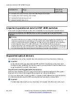
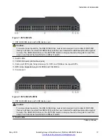
Page 17: ...s Avaya 1G SFPs and 100Base low speed SFPs 5 SFP slots Supports Avaya s 1G SFPs and 10G SFP s 6 Console port Figure 2 VSP 4850GTS PWR 1 VSP 4000 USB device with USB device cover Caution To ensure proper operation the USB FLASH drive must remain inserted in all models of VSP 4850 factory built and converted from ERS 4850 with the cover installed for additional protection against removal The USB FLA...

Page 18: ...y built and converted from ERS4850 must be treated as a permanent non removable part of the switch and must NEVER be removed from the switch to ensure proper operation Additionally the USB cover must be installed to ensure additional protection against removal The USB FLASH drive on the VSP 4850 switch is uniquely and permanently bound to the operating system of the switch it is first used on and ...

Page 19: ...onnect data cables to the device Always use antistatic wrist straps Make sure you adjust the strap to provide good skin contact Ensure that you properly ground work surfaces and equipment racks for protection against electrostatic discharge You must connect the common point to the building ground wire In a properly wired building the nearest reliable ground is typically at the electrical outlet Av...

Page 20: ...ns for the individual switches in this series Ensure that the area where you install the switch and where it operates meets these requirements Warning To avoid bodily injury from hazardous electrical shock and current never remove the top of the device No user serviceable components are inside Table 3 Physical specifications Specifications 4850GTS 4850GTS DC 4850GTS PWR Height 4 4 cm 1RU 4 4 cm 1R...

Page 21: ...ss than or equal to 45 db at 35 C and less than or equal to 57 db at 50 C The temperature is allowed to have 3 5 C deviation around the threshold of 35C measurement methods based on ISO 7779 Miscellaneous Operating Considerations No heat sources such as hot air vents or direct sunlight near the switch No sources of severe electromagnetic interference near the switch No excessive dust in the enviro...

Page 22: ...ith an IEC 60320 C16 connector Note A power cord is not included for the A variant of the switch 5 Documentation that includes the following a Locating the latest software and product release notes for Avaya Virtual Services Platform 4000 Series NN46251 106 b Avaya Virtual Services Platform 4000 Series Regulatory Guide NN46251 105 c Avaya Virtual Services Platform 4000 Series 4850GTS Series Quick ...

Page 23: ...factory built and converted from ERS 4850 with the cover installed for additional protection against removal The USB FLASH drive on the VSP 4850 switch is uniquely bound to the system it was first used on and cannot be transferred to a different switch 2 Attach the included rubber footpads on the bottom of the switch at the locations indicated 3 Set the switch on a table or shelf as illustrated be...

Page 24: ...ectly on top of one another You must secure each unit to the rack with the appropriate mounting brackets Mounting brackets cannot support multiple units For a translation of this statement see Translations of safety messages on page 41 1 Remove the screws that hold the USB cover but do not remove the USB cover Caution To ensure proper operation the USB FLASH drive must remain inserted in all model...

Page 25: ...the USB cover 3 Slide the switch into the rack as illustrated 4 Insert and tighten the rack mount screws Installing the Avaya Virtual Services Platform 4000 in an equipment rack May 2016 Installing Avaya Virtual Services Platform 4850GTS Series 25 Comments on this document infodev avaya com ...

Page 26: ... a serial cable with RJ 45 connectors or a serial cable with a DB 9 female connector on one end and an RJ 45 on the other is appropriate The maximum length for the console port cable is 25 feet 8 3 meters SFP Transceiver Ports Varies with the installed SFP transceiver See the documentation shipped with the SFP transceiver for specifications USB Port The USB port is not user accessible on the VSP 4...

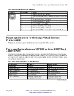
Page 27: ...dule slot use a gentle side to side rocking motion while firmly pulling the transceiver from the slot 5 Attach a dust cover over the fiber optic bores and store the transceiver in a safe place until you need it Important Discard transceivers in accordance with the proper laws and regulations RJ 45 connector pin assignments The following section describes the connector pin assignments for the RJ 45...

Page 28: ... MDI X in IEEE802 3at Console port pin assignments The following table describes the console port pin assignments in the Avaya VSP 4000 Important Avaya VSP 4000 supports only CLI Quickstart use on the console port Table 7 DB 9 Console port pin assignments Connector Pin Number Signal 1 Carrier detect not used 2 Transmit Data TXD 3 Receive Data RXD 4 Data terminal ready not used 5 Signal ground GND ...

Page 29: ...l Services Platform 4000 Series 4850GTS and 4850GTS PWR switches The regulatory power specifications are based on the maximum rated capacity of the power supplies and are not based on typical power consumption which is lower Table 9 AC power specifications for 4850GTS series Specifications 4850GTS 4850GTS PWR Input Current 5A 2 5 A 12A 6A Input Voltage rms 100 to 240 VAC at 50 to 60 Hz 100 to 240 ...

Page 30: ... 300 W Input voltage 48 V DC Input current 10 A Output voltage 12 V DC Output current 25 A VSP 4000 power supply power specification The VSP 4000 supports two external field replaceable power supplies One power supply ships with the chassis You can install a secondary power supply to provide redundancy and load sharing and to add Power over Ethernet Plus PoE power budget on PWR models 300 W AC pow...

Page 31: ...11 Avaya VSP 4850GTS and 4850GTS PWR models Maximum PoE W Average PoE W on 50 port model 855 W with one power supply 1855 W with two power supplies 15 4 W 802 3af 17 8 W 802 3 at One power supply 32 4 W 802 3at Two power supplies VSP 4850GTS PWR can support 802 3af 15 4 W on each port with one power supply installed You can add a second power supply for redundancy VSP 4850GTS PWR can support 802 3...

Page 32: ...port two field replaceable external power supplies If supported you can install an optional second power supply for redundancy load sharing or to provide additional PoE power budget Perform the following procedure to install an external power supply into your switch Note Avaya VSP 4000 hardware can vary This procedure only applies to hardware models with field replaceable power supplies 1 If a bla...

Page 33: ...he switch you need an appropriate AC power cord as described in the following table also see the following table for plug specifications Table 14 International power cord specifications Country and Plug Specification Specifications Typical Plug Continental Europe CEE7 standard VII male plug Harmonized cord HAR marking on the outside of the cord jacket to comply with the CENELEC Harmonized Document...

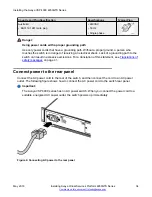
Page 34: ...ee Translations of safety messages on page 41 Connect power to the rear panel Connect the AC power cord to the rear of the switch and then connect the cord to an AC power outlet The following figure shows how to connect the AC power cord to the switch rear panel Important The Avaya VSP 4000 series has no AC power switch When you connect the power cord to a suitable energized AC power outlet the sw...

Page 35: ...1 enable VSP 4450GSX PWR 1 sys shutdown Are you sure you want shutdown the system Y N y n y CP1 03 24 14 18 39 04 932 UTC 0x00010813 00000000 GlobalRouter HW INFO System shutdown initiated from CLI CP1 03 24 14 18 39 06 000 LifeCycle INFO Stopping all processes CP1 03 24 14 18 39 08 000 LifeCycle INFO All processes have stopped CP1 03 24 14 18 39 08 000 LifeCycle INFO All applications shutdown sta...

Page 36: ...95413 989531 System Halted OK to turn off power Check Light Emitting Diode LED on the Avaya Virtual Services Platform 4000 The figures and tables in the following sections describe the LEDs on the Avaya Virtual Services Platform 4000 switches The tables describe LED operation for a switch that finishes the power on self test Front panel LEDs The following diagrams illustrate the components on the ...

Page 37: ...rts Avaya 1G SFPs and 100Base low speed SFPs 5 SFP slots Supports Avaya s 1G SFPs and 10G SFP s 6 Console port Warning Fiber optic equipment can emit laser or infrared light that can injure your eyes Never look into an optical fiber or connector port Always assume that fiber optic cables are connected to a light source For a translation of this statement see Translations of safety messages on page...

Page 38: ... running diagnostic software Normal activity during boot process Off The switch failed the power on self test POST or failed to load the agent code RPS Green solid The switch is connected to a redundant power supply unit RPS or a secondary external power supply and is operating normally Green blinking The switch is connected to a secondary power supply but the power input is disconnected Amber sol...

Page 39: ...e port is set to operate at 10 Mbps for all models Link Activity Green Steady The link established but no data activity exists Green Blink The link is established and data activity exists the blink rate indicates the level of activity Green Slow Blink The port is administratively disabled Off Local remote fault Table 17 SFP SFP transceiver Port LED state indicators Label Color and Status Descripti...

Page 40: ...sh a link Connect ports using the same set speed or use auto negotiation on each switch The port Link Activity LEDs graphically represented in EDM are always steady once a link is established They do not blink to reflect port traffic activity Installing the Avaya VSP 4000 4850GTS Series May 2016 Installing Avaya Virtual Services Platform 4850GTS Series 40 Comments on this document infodev avaya co...

Page 41: ...ectement sur un autre Chaque module doit être fixé à sa propre baie à l aide des supports de montage appropriés Ces supports ne sont pas conçus pour résister à plusieurs modules Important Precautión Cuando monte este dispositivo en un bastidor no apile las unidades directamente una encima de otra Cada unidad debe fijarse en el bastidor con las abrazaderas de montaje adecuadas Las abrazaderas de mo...

Page 42: ...laisser la plaque métallique sur la baie Si vous la retirez l aération du module ne peut pas s effectuer correctement Important Precaution Si no instala ningún módulo en la ranura asegúrese de mantener la placa de la cubierta de metal en la misma Si la retira impedirá que el aire circule y la unidad se refrigere adecuadamente Important Attenzione Se nello slot non vengono installati moduli assicur...

Page 43: ...s d urgence Important Advertencia Para apagar el dispositivo debe desenchufar el cable Conecte siempre el cable de alimentación a una toma segura y de fácil acceso por si se produjera alguna situación de emergencia Important Avviso L unico modo per disattivare questo dispositivo consiste nello scollegare il cavo di alimentazione Collegare sempre il cavo di alimentazione ad una presa che sia facilm...

Page 44: ... messa a terra Senza un adeguata messa a terra chiunque tocchi lo switch corre il rischio di ricevere una scossa elettrica L assenza di un percorso per la messa a terra verso lo switch può comportare un eccesso di emissioni Warning The lithium battery is not field replaceable It must only be removed and replaced by authorized personnel Contact Avaya Technical Support for assistance if the battery ...

Page 45: ...não é substituível em campo Só deve ser removida e substituída por pessoal autorizado Entre em contato com o Suporte Técnico da Avaya para obter assistência se a bateria precisar de substituição Important Предупреждение Литиевые аккумуляторы не подлежат самостоятельной замене в условиях эксплуатации Их может извлекать и заменять только аттестованный персонал Если требуется замена аккумулятора обра...

Reviews: