background image

17

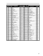
ITEM

PART Nº

DESCRIPTION

QTY SPARES

45

07003-00087

● 

SEAL

1

1

46

07002-00017

● 

NUT

1

1

47

07500-00705

● 

PISTON INSERT

1

-

48

07004-00038

● 

CIRCLIP

1

1

49

07500-00706

● 

AIR PISTON

1

-

50

07500-00203

● 

PISTON BUFFER

1

1

51

07500-00702

● 

HANDLE INSERT

1

-

52

07500-01400

● 

INTENSIFIER ROD ASSY

1

-

53

07500-01700 CYLINDER HEAD SUB-ASSY 

1

-

54

07003-00001 'O' RING 

2

2

55

07005-00015 COPPER WASHER

1

2

56

07500-00041 DOUBLE MALE CONNECTOR

1

1

57

07003-00098 SEAL

1

5

58

07500-00215 PRIMING NIPPLE

1

1

59

07007-00284 VALVE CAP

1

2

60

07005-00088 VALVE

1

1

61

07003-00099 SEAL

1

1

62

07003-00080 BACKUP RING

1

1

63

07500-04100 REAR PINTAIL DEFLECTOR 

1

1

64

07001-00007 SCREW

1

1

65

07500-00216 GASKET

1

1

66

07003-00033 SEAL

4

4

67

07001-00059 SCREW

4

1

68

07500-00201 AIR CYLINDER

1

-

69

07500-00203 PISTON BUFFER

1

1

70

07004-00038 CIRCLIP

1

1

71

07003-00082 'O' RING 

1

1

72

07003-00025 'O' RING

1

1

73

07001-00116 SCREW

12

3

74

07500-00211 HEAD GASKET

1

1

75

07500-00205 ANTI-EXTRUSION RING

1

2

76

07003-00084 'O' RING 

1

1

77

07003-00090 SPIRAL BACK UP RING

2

2

78

07003-00089 'H' RING SEAL

1

1

79

07500-00206 VALVE OPERATING ROD

1

1

80

07003-00106 WIPER RING

1

1

81

07500-00212 NOSE RETAINING NUT

1

1

82

07500-01902 FOAM SILENCER

1

-

83

07500-00207 L.H. COVER

1

-

84

07001-00117 SCREW

6

2

85

07002-00033 SPRING WASHER

6

2

86

07500-00210 R.H. COVER

1

-

87

07500-01903 FOAM SILENCER

1

-

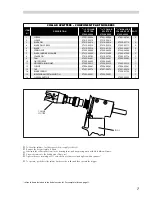
07500-00200 PARTS LIST

ITEM

PART Nº

DESCRIPTION

QTY SPARES

1

07500-01900 HEAD & HANDLE SUB-ASSY

1

-

2

07001-00004

● 

SCREW

1

1

3

07003-00108

● 

SEAL

1

1

4

07003-00101

● 

WIPER RING

1

5

5

07003-00082

● 

'O' RING 

1

1

6

07500-00800

● 

TRIGGER SUB-ASSY

1

-

7

07007-00063

● 

PIN

1

5

8

07004-00039

● 

CIRCLIP

1

1

9

07500-00304

● 

RETAINING WASHER

1

1

10

07003-00107

● 

SEAL

1

1

11

07003-00096

● 

SPIRAL BACK UP RING

1

1

12

07500-00306

● 

HEAD PISTON 

1

-

13

07500-00313

● 

FRICTION RING

1

5

14

07500-00316

● 

HEAD END CAP

1

-

15

07500-00310

● 

FRONT PINTAIL DEFLECTOR

1

5

16

07001-00115

● 

SCREW

3

3

17

07500-01901

● 

HANDLE 1

-

18

07003-00014

● 

SPIRAL BACK UP RING

2

2

19

07003-00093

● 

SEAL

1

1

20

07500-00314

● 

SEAL HOUSING

1

-

21

07500-00317

● 

INSERT RETAINER

1

-

22

07001-00114

● 

SCREW

2

4

23

07003-00033

● 

SEAL

2

4

24

07500-01800 CYLINDER HEAD ASSY

1

-

25

07003-00120

● 

'O' RING 

1

1

26

07500-04200

● 

RESERVOIR VALVE ASSY

1

-

27

07003-00032

● 

'O' RING 

1

1

28

07500-06500

● 

RESERVOIR PISTON ASSY

1

-

29

07220-02103

● 

SPRING

1

1

30

07500-00403

● 

VALVE 'O' RING WASHER

4

-

31

07500-00407

● 

REAR VALVE SEAT

1

-

32

07500-00418

● 

SPRING

1

1

33

07001-00118

● 

SCREW

1

1

34

07003-00103

● 

'O' RING 

4

4

35

07500-00401

● 

VALVE STEM

1

-

36

07500-00404

● 

'O' RING SPACER 

2

-

37

07003-00086

● 

'O' RING 

2

2

38

07500-00406

● 

FRONT VALVE SEAT

1

-

39

07500-00402

● 

VALVE STEM  EXTENSION

1

-

40

07500-01300 AIR PISTON ASSY

1

-

41

07003-00109

● 

SEAL 1

5

42

07003-00006

● 

SPIRAL BACK UP RING

1

1

43

07500-00704

● 

RETAINING PLATE

1

-

44

07500-00703

●  

AIR BLEED INSERT

1

-

Summary of Contents for 07500

Page 1: ...al Technologies Company 0Instruction Manual Pass onto user to read and keep for reference Hydro Pneumatic Power Tool 07500 Instruction Manual Hydro Pneumatic Power Tool Pass onto user to read and keep...

Page 2: ...dB A WEIGHT Without nose equipment 3 85 kg 8 47 lb VIBRATION Less than 2 5 m s2 8 ft s2 AIR PRESSURE Minimum Maximum 5 5 7 bar 80 100 lbf in2 FREE AIR VOLUME REQUIRED 5 5 bar 80 lbf in2 5 7 litres 20...

Page 3: ...rocedure 18 19 FAULT DIAGNOSIS Fault Diagnosis Table 20 1 Priming Oil Details 18 Priming Procedure 18 19 Selection Fitting Servicing Components 8 10 Air Supply 5 Operating Procedure 5 Accessories 6 7...

Page 4: ...s ENSURE THAT VENT HOLES DO NOT BECOME BLOCKED OR COVERED AND THAT HOSES ARE ALWAYS IN GOOD CONDITION 2 SA F E T Y 2 This instruction manual must be read with particular attention to the following saf...

Page 5: ...IC OIL SHOULD BE AVOIDED TO MINIMIZE THE POSSIBILITY OF RASHES CARE SHOULD BE TAKEN TO WASH THOROUGHLY 3 3 In addition to the general safety rules opposite the following specific safety points must al...

Page 6: ...5 6 Dimensions shown in bold are millimetres Other dimensions are in inches 4 143 5 6 The hydro pneumatic 07500 type tool is designed to place Avdelok Pins and collars at high speed making it ideal fo...

Page 7: ...ushing itself off the collar and ejecting the pin tail at the rear 5 5 PU T T I N G I N T O S E R V I C E A I R S U P P L Y All tools are operated with compressed air at an optimum pressure of 5 4 bar...

Page 8: ...R SPLITIER 07500 06800 07500 06900 MAXLOK COLLAR SPIIITER 07500 05900 6 6 A C C E S S O R I E S These are the accessories available for the 07500 00200 tool Three of which are to make the connection w...

Page 9: ...er refers to items included in the Avdel service kit For complete list see page 11 7 7 refers to items included in the Avdel service kit For complete list see page 11 To fit collar splitters first dis...

Page 10: ...over the chuck collet Slide nose retaining nut over anvil 1 and screw onto front of tool 8 FITTING INSTRUCTIONS Nose assemblies must be assembled before fitting Offset nose assemblies are always supp...

Page 11: ...der to dismantling refers to items included in the Avdel service kit For complete list see page 11 9 9 refers to items included in the Avdel service kit For complete list see page 11 To fit Offset Hea...

Page 12: ...5 07500 00313 07500 02208 1 1 1 1 1 1 1 1 1 1 1 1 10 2 3 1011 ill i 11111 iii __ 11 it I III 9 Till lam 8 4 7 6 5 10 NOSE ASSEMBLY COMPONENTS 10 1 GUIDE TUBE 07500 02209 1 2 EXTERNAL CIRCLIP 07004 000...

Page 13: ...burning or disposal on approved site Away from heat and oxidising agent 11 SE R V I C I N G T H E T O O L Regular servicing should be carried out and a comprehensive inspection performed annually or e...

Page 14: ...d nose assemblies follow a similar procedure refer to nose equipment section pages 8 11 12 Every 500 000 cycles the tool should be completely dismantled and new components should be used where worn da...

Page 15: ...er to dismantling refers to items included in the Avdel service kit For complete list see page 11 13 13 refers to items included in the Avdel service kit For complete list see page 11 TRIGGER AND VALV...

Page 16: ...ervicing Priming is ALWAYS necessary after the tool has been dismantled and prior to operating 14 AIR PISTON ASSEMBLY Ensure oil is drained from the tool Remove air cylinder 68 as described earlier Us...

Page 17: ...15 15...

Page 18: ...0 84 85 86 87 24 53 4 54 55 56 57 25 26 22 D 4 Ii 37 27 83 82 16 16 GENERAL ASSEMBLY OF BASE TOOL 07500 00200 38 39 49 71 48 47 46 70 69 68 50 72 73 74 51 75 76 52 77 A A B 78 79 6 7 8 9 10 11 80 81 1...

Page 19: ...VER 1 43 07500 00704 RETAINING PLATE 1 87 07500 01903 FOAM SILENCER 1 44 07500 00703 AIR BLEED INSERT 1 17 17 ITEM PART N DESCRIPTION QTY SPARES 45 07003 00087 SEAL 1 1 46 07002 00017 NUT 1 1 47 07500...

Page 20: ...issues from the rear bleed hole Replace and tighten rear bleed screw 84 18 ENVIRONMENT WASTE DISPOSAL Through authorised contractor to a licensed site May be incinerated Used product may be sent for r...

Page 21: ...ls to attain full stroke or will not place bolts after this procedure use the following procudure 19 19 Top up priming pump and operate until resistance is felt Remove priming pump Tighten front bleed...

Page 22: ...lows and fails to actuate Exhaust silencer dirty 0 Clean silencer o Air in oil 0 Reprime tool see page 18 20 20 FA U L T D I A G N O S I S F A U L T D I A G N O S I S T A B L E SYMPTOM POSSIBLE CAUSE...

Page 23: ...strated within this publication are subject to patent design or copyright protection in many countries Products mentioned and or illustrated within this publication are subject to patent design or cop...

Page 24: ...l infoAvdel USA acument com Avdel UK Limited 2007 Manual No Issue Change Note No 07900 00391 B 07 325 www avdel global com Manual No Issue Change Note No 07900 00391 B 07 325 Avdel UK Limited 2007 AUS...

Reviews: