14
Servicing the Tool
Assembly Instructions
•
All 'O' rings and seals should be renewed and lubricated with Molykote® 55m* for pneumatic sealing or Molykote® 111* for hydraulic
sealing.
Head Assembly
•
Using soft jaws to hold the tool Handle, position the tool in the nose-down orientation.
•
Install Bearing Ring
54
, Lip Seal
17
, Wiper
18
and 'O' Ring
23
on to Seal Housing
52
.
•
Fit Anti-extrusion Rings
20
to both seal grooves on Head Piston
64
. Anti-extrusion Rings should be installed in seal grooves close to breather
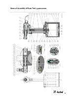
hole into Head Piston, as shown in Detail 'C' on General Assembly drawing.
•
Fit Head Piston Seals
19
to both seal grooves on Head Piston
64
. Head Piston Seals should be installed in seal grooves furthest from breather
hole into Head Piston, as shown in Detail 'C' on General Assembly drawing.
•
Fit Head Piston Bullet* to Head Piston
64
and load Seal Housing assembly on to Head Piston.
•
Before inserting Head Piston
64
into Head
63
fit Head Piston Seal Guide* to rear of Head. Once Head Piston
64
is installed in the fully
forward position, remove Head Piston Seal Guide and Head Piston Bullet.
•
Before inserting Lip Seal
21
into Head
63
fit Rear Head Piston Bullet* to Head Piston
64
and Rear Lip Seal Sleeve* to rear of Head. Use Rear
Lip Seal Plunger* to insert Lip Seal up to stop.
•
Install Bearing Ring
53
, Wiper
22
and 'O' Ring
6
into End Cap
51
.
•
Apply Loctite® 243* to thread of End Cap
51
and using 48mm A/F spanner screw End Cap into Head
63
.
•
Fit Head Vice Jaw* to Head
63
and use soft jaws to hold the Head Vice Jaw in the inverted orientation.
•
Fit Lip Seal
14
on to Return Piston
57
.
•
Fit Return Piston on to Return Piston Extractor* and insert into Head
63
to depth mark indicated on Return Piston Extractor.
•
Apply Loctite® 243* to thread of Air Piston Rod End
59
. Fit 4mm A/F Allen key into Air Piston Rod
58
and use 14mm A/F spanner or 5mm A/F
Allen key to wind on Air Piston Rod End.
•
Fit Bearing Ring
60
on to Air Piston Rod End
59
.
•
Fit Air Piston Rod Bullet* to Air Piston Rod
58
and install Pull Piston
56
, Lip Seal
14
, Seal Stop
61
, Lip Seal
15
and Bearing Ring
62
in
orientation and order shown on General Assembly.
•
Insert Air Piston Rod assembly into Head
63
.
•
Install Lip Seal
16
and 'O' Ring
12
into Seal Retainer
55
.
•
Apply Loctite® 243* to thread of Seal Retainer
55
and use Seal Retainer Wrench* to wind into Head
63
.
•
Remove Air Piston Rod Bullet*.
•
Fit 2 'O' Rings
13
on to Head
63
.
•
Install Trigger Valve
28
using Trigger Valve Extractor*.
•
Fit Trigger
29
and insert Trigger Pin
30
into Head
63
.
•
Remove the Head Vice Jaw*. Using soft jaws to hold the tool Handle, position the tool in the nose-down orientation.
•
Fit 4 Bleed Screws
1
and 4 Bonded Seals
5
to seal bleed ports.
Body Assembly
•
Fit Head Vice Jaw* to Head
63
and use soft jaws to hold the Head Vice Jaw in the inverted orientation.
•
Fit Body
65
on to Head
63
.
•
Apply Loctite® 243* to thread of Handle Retaining Nut
34
and wind on to Handle
63
using Handle Retaining Nut Wrench* to tighten.
•
Apply Loctite® 243* to thread of Air Piston Rod
58
and wind Air Piston Connector
41
on to Air Piston Rod. Tighten using 4mm A/F Allen key
in Air Piston Rod and 14mm A/F spanner on Air Piston Connector.
•
Fit Quad Seal
9
and Force Reduction Seal
35
to Air Piston
33
.
•
Insert Air Piston
33
into Body
65
until it fits on to Air Piston Connector
41
.
•
Apply Loctite® 243* to thread of Air Piston Connector
41
. Tighten Nut
3
using 27mm A/F Spanner with 14mm A/F spanner or 5mm A/F Allen
key on Air Piston Connector to prevent rotation.
•
Fit 'O' Ring
8
on to Base Plate
32
.
•
Insert Base Plate
32
into Body
65
and install Retaining Ring
24
.
•
Thoroughly clean Silencer
37
or renew if worn. Fit Silencer to Base Cap
31
and install Retaining Ring
25
.
•
Place Gasket
36
on to Base Cap
31
and fit on to Body
65
.
•
Screw Locknut
38
on to Base Plate
32
using Locknut Socket*. If necessary, use a 10mm A/F Allen key to prevent rotation of Base Plate.
Operating Valve
•
Fit 2 'O' Rings
10
into Valve Body
42
and 2 'O' Rings
11
on to Valve Body.
•
Insert Valve Body
42
into Body
65
.
•
Fit 2 'O' Rings
11
on to Valve Spool
39
.
•
Insert Valve Spool
39
into Body
65
.
•
Fit 'O' Ring
7
to Valve Retainer
40
.
•
Apply Loctite® 243* to thread of Valve Retainer
40
and use 6mm A/F Allen key to install Valve Retainer into Body
65
.
•
Fit 2 'O' Rings
4
on to Swivel Bolt
44
.
•
Fit Swivel
43
on to Swivel Bolt
44.
•
Apply PTFE Tape to thread of Swivel Bolt
44
and using 22mm A/F spanner or socket, wind Swivel Bolt into Body
65
.
•
Fit Adaptor
48
, Adaptor Ring
50
, Retaining Nut
49
and Deflector
47
.
* Refers to items included in 73200 Service Kit. For complete list see page 12.
Item numbers in
bold
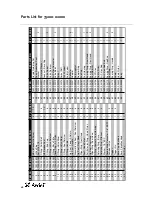
refer to the General Assembly drawing and parts list (pages 15 – 16).


