background image


18


Priming 

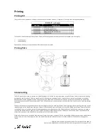
Priming Kit 

 
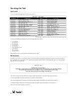
The 73200 Service Kit includes all of the parts needed to prime the tool. However, if required, a Priming Kit can be supplied separately. 
 

PRIMING KIT : 73200-99991 

PART NO. 

DESCRIPTION 

QTY. 

07900-01060 

PRIMING SYRINGE 

07900-01061 

PULL STROKE SETTER 

07900-01062 

RETURN STROKE SETTER 

07900-01063 

PRIMING SYRINGE EXTENSION 

07900-01066 

STARTER NUT 

 
To fit the Pull Stroke Setter and Return Stroke Setter, the following standard tools are needed (not supplied with Priming Kit). 


27mm Spanner 


10mm Allen key 

 
Spanners and Allen keys are specified across flats unless otherwise stated. 
 

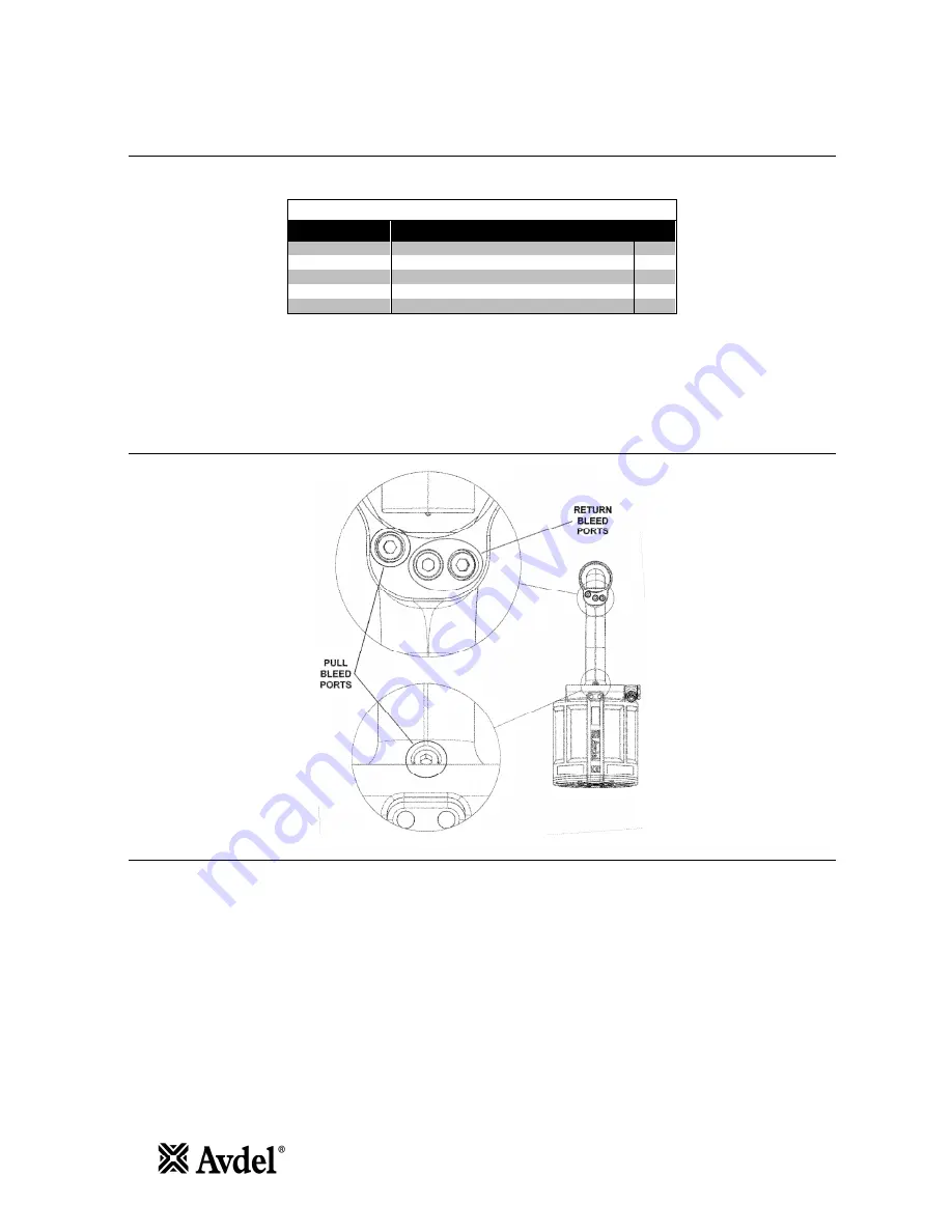
Priming Ports 


Stroke Setting 

 
The Pull Stroke Setter is used to advance the Head Piston 

64

 to full stroke. The external threads on the Pull Stroke Setter wind into the Head 

63

pushing the Head Piston back. With the Head Piston fully forward, only one side of the Pull Stroke Setter will wind into the Head, as the Head 
Piston prevents thread engagement when using the other side. When the Pull Stroke Setter is wound up to a stop in the Head, the Head Piston 
has been advanced to half of the available stroke. The Pull Stroke Setter is then unscrewed and the other side is wound into the Head, completing 
the stroke. 
 
The Return Stroke Setter is used to draw the Head Piston 

64

 fully forward. The Return Stroke Setter stops against the Head 

63

, whilst the internal 

threads wind on to the Head Piston, drawing it forward. With the Head Piston at full stroke, only one side of the Return Stroke Setter will wind on 
to the Head Piston, as the Head prevents thread engagement when using the other side. When the Return Stroke Setter is wound up to a stop in 
the Head, the Head Piston has been returned to approximately half of the available stroke. The Return Stroke Setter is then unscrewed and the 
other side is wound on to the Head Piston, returning it to the fully forward position. 
 
When either Setter is used, the Head Piston should not rotate. If necessary, a 10mm A/F Allen key should be fitted to the rear of the Head Piston to 
prevent rotation. It may be necessary to move the Head Piston forward with the Starter Nut to allow the Return Stroke Setter to engage the 
thread. 
 

* Refers to items included in 73200 Service Kit. For complete list see page 12. 

Item numbers in 

bold

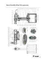
 refer to the General Assembly drawing and parts list (pages 15 – 16). 

Summary of Contents for 73200 Tool

Page 1: ...Instruction Manual Original Instruction 73200Tool Hydro Pneumatic PowerTool ...

Page 2: ...2 ...

Page 3: ...will be free of defects in workmanship and materials which occur under normal operating conditions This Limited Warranty is contingent upon 1 the product being installed maintained and operated in accordance with product literature and instructions and 2 confirmation by Avdel of such defect upon inspection and testing Avdel makes the foregoing limited warranty for a period of twelve 12 months foll...

Page 4: ...s disconnect the airline from the tool machine inlet before attempting to adjust fit or remove a nose assembly 8 Do not operate a tool machine that is directed towards any person s or the operator 9 Always adopt a firm footing or a stable position before operating the tool machine 10 Ensure that vent holes do not become blocked or covered and that hoses are always in a good condition 11 The operat...

Page 5: ...e followed at all times Tool Specification Air Pressure Minimum Maximum 5 0 7 0 bar 73 102 lbf in2 Free Air Volume Required 5 0 bar 73 lbf in2 14 2 litres 7 0 bar 102 lbf in2 19 9 litres Stroke Minimum 20 mm 0 79 in Pull Force 5 0 bar 73 lbf in2 25 9 kN 5823 lbf 7 0 bar 102 lbf in2 36 2 kN 8138 lbf Cycle Time Approximately 3 seconds Noise Level Less than LAeq T 75 dB A Weight Without nose equipmen...

Page 6: ... pintail to eject from the nose at a high speed and force When installing lockbolt products Ensure that the correct nose assembly is fitted Connect the tool to the air supply Push the Avdelok pin through the application hole Place the collar on the pin orientate as shown Keeping the head of the pin against the application push the tool on to the protruding pin tail Fully depress the trigger One cy...

Page 7: ...e deformation of the collars thus allowing placing of Avdelok in softer materials like plastics wood etc Standard Nose Assembly Selection The fasteners below can also be placed on the 73200 tool It is essential that the correct nose assembly is fitted prior to operating the tool STANDARD NOSE ASSEMBLY SELECTION FASTENER NOSE EQUIPMENT NAME Ø DESCRIPTION PART NO AVBOLT 3 16 4 8mm Refer to 07900 009...

Page 8: ...S Lightly coat the jaws with Moly Lithium grease Assemble Spring Guides 4 and Spring 5 Balance the three Chuck Jaws 3 on the upper Spring guide 4 using a spent pintail to aid positioning if necessary Carefully lower Chuck Collect 2 over the assembled components Insert Spacer 6 if required into Chuck Collet 2 5 16 dia only Assembly can then be located in anvil Item numbers in bold refer to the draw...

Page 9: ...h the collar splitter hard over the collar and depress the trigger To cut 5 16 or 3 8 Avdelok use 07220 03700 and 07220 03900 collar splitters respectively no adaptor kit is required Fit Head Vice Jaw to Head 63 and use soft jaws to hold the Head Vice Jaw in the inverted orientation Use Locknut Socket to unscrew Locknut 38 If necessary use a 10mm A F Allen key to prevent rotation of Base Plate 32 ...

Page 10: ...or 47 is fitted to the tool Check the stroke of the tool meets the minimum specification page 5 The last steps of the Priming Procedures on pages 19 and 20 explain how to measure the stroke Check that the anvil is not worn This can be confirmed by referring to the installed data on the fastener datasheet Excessive wear can cause the anvil to rupture Weekly 1 Dismantle and clean the nose assembly w...

Page 11: ...ver due to the physical form and water insolubility of the product the bioavailability is negligible Handling General ventilation is recommended Avoid skin and eye contact Storage Do not store with oxidizing agents Keep container closed and store away from water or moisture Molykote 111 Grease Safety Data First Aid SKIN No first aid should be needed INGESTION No first aid should be needed EYES No ...

Page 12: ...eparately For servicing the following standard tools are needed not supplied with Service Kit 4mm Allen key 5mm Allen key 6mm Allen key 10mm Allen key 14mm Spanner 22mm Spanner or Socket 27mm Spanner 48mm Spanner 10mm PTFE Tape Spanners and Allen keys are specified across flats unless otherwise stated Maintenance Annually or every 500 000 cycles whichever is sooner the tool should be completely di...

Page 13: ...spanner unscrew Air Piston Connector 41 Push Air Piston Rod into Head 63 up to stop Using Handle Retaining Nut Wrench unscrew Handle Retaining Nut 34 and remove Body 65 Head Assembly Remove 4 Bleed Screws 1 and Bonded Seals 5 and drain oil into a suitable container Fit Head Vice Jaw to Head 63 and use soft jaws to hold the Head Vice Jaw in the inverted orientation Remove O Rings 13 from Head 63 Us...

Page 14: ...l Retainer 55 Apply Loctite 243 to thread of Seal Retainer 55 and use Seal Retainer Wrench to wind into Head 63 Remove Air Piston Rod Bullet Fit 2 O Rings 13 on to Head 63 Install Trigger Valve 28 using Trigger Valve Extractor Fit Trigger 29 and insert Trigger Pin 30 into Head 63 Remove the Head Vice Jaw Using soft jaws to hold the tool Handle position the tool in the nose down orientation Fit 4 B...

Page 15: ...15 General Assembly of BaseTool 73200 02000 ...

Page 16: ...eal Handle 1 6 48 73200 02041 Adaptor 1 1 16 07003 00477 Pneumatic Lip Seal Seal Retainer 1 6 49 73200 02042 Retaining Nut 1 17 07003 00478 Lip Seal Front Head 1 6 50 73200 02043 Adaptor Ring 1 18 07003 00479 Wiper Ring Front Head 1 6 51 73200 03101 End Cap 1 19 07003 00482 Seal Head Piston 2 6 52 73200 03102 Seal Housing 1 1 20 07003 00483 Anti Extrusion Ring Head Piston 2 6 53 73200 03103 Bearin...

Page 17: ... requires no immediate attention Short term contact requires no immediate attention INGESTION Seek medical attention immediately DO NOT induce vomiting EYES Irrigate immediately with water for several minutes Although NOT a primary irritant minor irritation may occur following contact Fire Flash point 232 C Not classified as flammable Suitable extinguishing media CO2 dry powder foam or water fog D...

Page 18: ...een advanced to half of the available stroke The Pull Stroke Setter is then unscrewed and the other side is wound into the Head completing the stroke The Return Stroke Setter is used to draw the Head Piston 64 fully forward The Return Stroke Setter stops against the Head 63 whilst the internal threads wind on to the Head Piston drawing it forward With the Head Piston at full stroke only one side o...

Page 19: ...ton is pushed back With the Head Piston at 21mm stroke remove Pull Stroke Setter Remove the Priming Syringe with Extension and reseal this port Return side priming Ensure tool is disconnected from air supply Ensure Extension is fitted to one Priming Syringe Fill both Priming Syringes with approximately 30ml of oil and remove any air from the syringes Fit Priming Syringe to return bleed port Fit Pr...

Page 20: ... Syringe with Extension and reseal this port Return side priming Connect tool to air supply This ensures the Air Piston 33 is at the end of the return stroke Disconnect tool from air supply Remove return bleed screws Ensure Extension is fitted to one Priming Syringe Fill both Priming Syringes with approximately 30ml of oil and remove any air from the syringes Fit Priming Syringe to return bleed po...

Page 21: ...rn anvil Replace 8 Tool requires priming Reprime tool 17 20 Swaging anvil cracked Replace 8 Incorrect length of bolt Change to correct length bolt Placing tool does not eject the collar from the anvil Reduced air pressure Adjust air pressure Check for leaks Oil level in tool low or air in oil Reprime tool 17 20 Worn or damaged hydraulic seals in tool Inspect tool replace worn or damaged seals 13 1...

Page 22: ... in conformity with the following standards EN ISO 12100 parts 1 2 BS EN ISO 8662 part 6 BS EN ISO 3744 Pneurop PN8NCT1 ISO EN 792 part 13 2000 BS EN ISO 11202 BS EN 982 BS EN 983 following the provisions of the Machine Directive 2006 42 EC A Seewraj Technology Manager Date of issue This box contains a power tool which is in conformity with Machines Directive 2006 42 EC The Declaration of Conformi...

Page 23: ...del UK Limited Pacific House 2 Swiftfields Welwyn Garden City Hertfordshire AL7 1LY Tel 44 0 1707 292 000 Fax 199 enquiries2 sbdinc com Avbolt Avdel Avdelok Avex Avinox Avseal Avtainer Hemlok Maxlok and Monobolt are trademarks of Avdel UK Limited The names and logos of other companies mentioned herein may be trademarks of their respective owners Data shown is subject to change without prior notice...

Reviews: