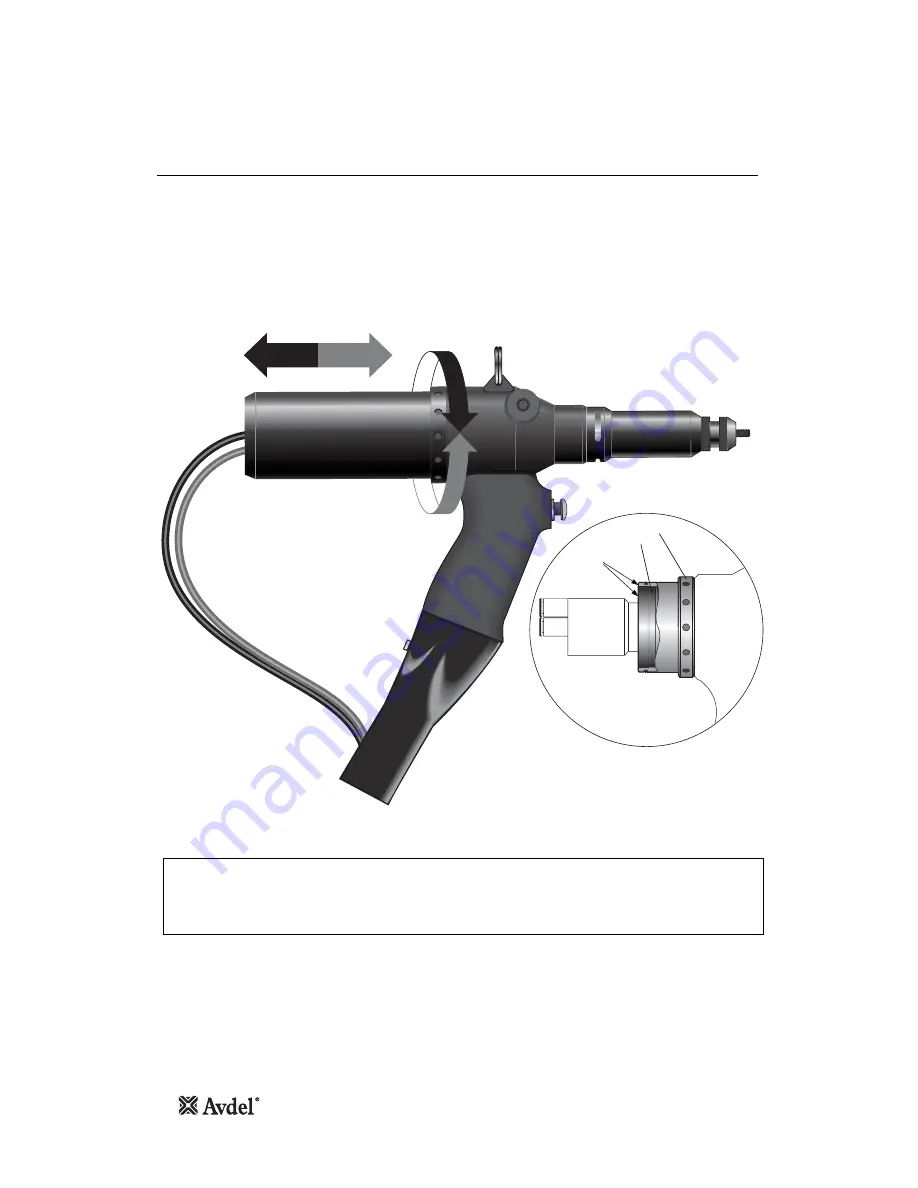
S t ro k e A d j u s t m e n t
P u t t i n g i n t o S e r v i c e
8
This adjustment is necessary to insure optimum insert deformation. It is suggested, therefore, that a test plate with the same thickness
and hole size as the workpiece is used.
If deformation is insufficient, the insert willl rotate inside the application.
If deformation is excessive, thread distortion will occur and possibly drive screw fracture.
The stroke is adjusted by the amount the Stroke Adjustment Lock Nut 12, (parts list page 17), is screwed in or out. To shorten the
stroke, screw in; to lengthen the stroke, unscrew the rear casing. Adjust until optimum deformation is obtained.
Item numbers in bold refer to the illustrations on pages 16 and 17.
I M P O R T A N T
At the correct stroke the rear faces of the Adjustment Ring 47 and the Stroke Adjustment Lock Nut 12 will be
flush.
The Adjustment Ring 47 must not be wound out beyond this point.
Note
47
12
Rear Casing (48)
Removed
Faces Flush
See
Note
Summary of Contents for 74405
Page 1: ...Hydro Pneumatic Power Tool 74405 Instruction Manual Original Instruction ...
Page 2: ......
Page 25: ...25 Notes ...
Page 26: ...26 Notes ...


