6
P
U T T I N G I N T O S E R V I C E
A I R S U P P L Y
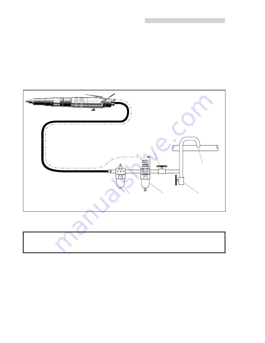
All tools are operated with compressed air at an optimum pressure of 5.5 bar. We recommend the use of pressure regulators and
automatic oiling/filtering systems on the main air supply. These should be fitted within 3 metres of the tool (see diagram below) to ensure
maximum tool life and minimum tool maintenance.
Air supply hoses should have a minimum working effective pressure rating of 150% of the maximum pressure produced in the system
or 10 bar, whichever is the highest. Air hoses should be oil resistant, have an abrasion resistant exterior and should be armoured where
operating conditions may result in hoses being damaged. All air hoses MUST have a minimum bore diameter of 6.4 millimetres or
1
/
4
inch.
Read servicing daily details page 10.
OPTION 2
Ensure that the correct nose assembly is fitted.
Connect the tool to the air supply.
Screw the insert lip first onto the drive screw of the tool.
With the insert on the tool, locate it into the prepared hole of
the application
Operate the throttle lever (item 30 page 15) and hold. The
drivescrew will screw and collapse the insert.
To release the tool from the insert, press the reverse valve
button (item 43 page 15) whilst still holding the throttle lever
down. The drivescrew will reverse out of the insert.
O P E R A T I N G P R O C E D U R E
I M P O R T A N T
When placing Standard Nutserts, lubricate the drive screw of the tool every 25 placings. This is best achieved by wiping
the drive screw with a sponge soaked with STP Lubricant part number 07992-00013
8
6
4
2
0
10
12
14
16
TAKE OFF POINT
FROM MAIN SUPPLY
STOP COCK
(USED DURING MAINTENANCE
OF FILTER/REGULATOR
OR LUBRICATION UNITS)
MAIN SUPPLY
DRAIN POINT
PRESSURE REGULATOR
AND FILTER
(DRAIN DAILY)
LUBRICATOR
3 METRES MAXIMUM
OPTION 1
Ensure that the correct nose assembly is fitted.
Connect the tool to the air supply.
Place the insert into the prepared hole of the application.
Locate the drive screw of the tool into the insert.
Operate the throttle lever (item 30 page 15) and hold. The
drivescrew will screw and collapse the insert.
To release the tool from the insert, press the reverse valve
button (item 43 page 15) whilst still holding the throttle lever
down. The drivescrew will reverse out of the insert.
■
■
■
■
■
■
■
■
■
■
■
■


