CLUTCH
Place tool handle and bush assembly
1
in vice fitted with soft jaws.
Unscrew clutch housing
35
(left hand thread) and remove bush
38
from clutch housing.
Withdraw clutch assembly, taking care not to bend push rod
30
.
Pull out push rod (long)
30
.
Remove tool from vice and gently tap on front end of assembly to remove needle roller
59
and push rod (short)
64
.
Holding square drive end of clutch spindle
43
, unscrew adjustment nut
28
.
Pull off adjustment lock washer
29
and spring
41
.
Depress spring
41
and remove pin
31
.
Remove collar
40
and three balls
39
.
Split retaining ring halves
32
.
Move front jaw
34
relative to clutch spindle
43
until small hole in side of front jaw
34
is aligned with track of balls
37
in clutch spindle
43
.
Ten balls
37
will become visible through small hole in front jaw
34
.
Gently tap front jaw
34
, allowing ten balls to fall out of hole in front jaw
34
(as each ball is ejected, turn front jaw
34
on clutch spindle
43
to align next ball with hole).
Insert small rod through centre of front jaw
34
and tap out clutch spindle
43
.
Remove drive jaw
33
, key
36
and spring
41
.
Clean and inspect components, renewing any worn or damaged items, paying special attention to condition of front jaw
34
and drive jaw
33
.
Assemble in reverse order to dismantling.
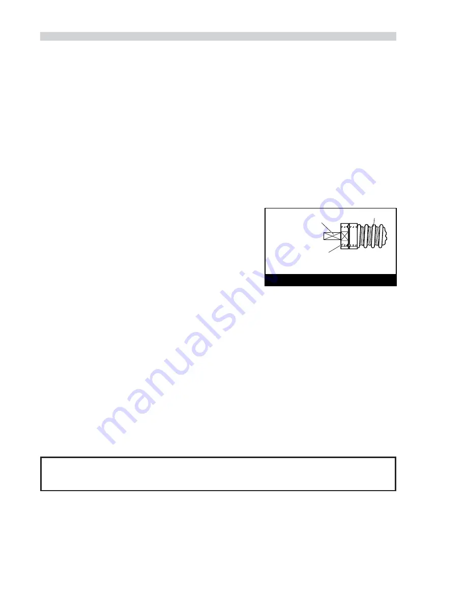
Reset clutch torque (dependant on clutch spring fitted : see page 7 ) in the
following manner (see diagram)
Place square drive on end of clutch spindle
43
in vice, engaging approximately
10mm in vice jaws. This allows for spanner entry.
Using a spanner, unscrew adjustment nut
28
until it is level with the end of the
thread of the clutch spindle. Torque can then be increased / decreased as dictated
by the fastener type and size by turning the adjustment nut clockwise/anticlockwise
as appropriate.
12
HANDLE ASSEMBLY
Replace handle and bush assembly
1
in soft jaw vice.
Using spanner on ring gear
44
, remove front remove front gear assembly.
Using spanner on housing
26
, remove inner gear assembly.
Remove ‘O’ ring
19
and spacer
18
from handle and bush assembly
1
and pull out motor assembly. (It may be necessary to tap the front
end of handle and bush assembly
1
on a wooden block until motor assembly slides out).
Unscrew silencer retainer assembly
9
and remove perforated washer
10
, silencer body
12
and silencer element
11
.
Unscrew nipple
8
from adaptor
7
.
Unscrew adaptor
7
from handle and bush assembly
1
and remove filter
6
.
Tap out pin
15
and carefully pull out trigger assembly, (take care not to damage ‘O’ rings).
Support trigger
17
and carefully drive out pin
16
taking care not to damage or bend valve
3
.
Separate trigger
17
from valve
3
and remove ‘O’ ring
14
, three ‘O’ rings
2
from valve body
13
and ‘O’ rings
4
&
5
from valve
3
.
Unscrew knob
75
and remove ‘O’ ring
67
from handle and bush assembly
1
.
Remove screw
73
and washer
74
.
Lightly tap end plate
70
to break Loctite seal between end plate
70
and valve assembly
65
.
Remove end plate
70
, taking care not to damage pins
72
.
Remove ‘O’ ring
71
and spring
69
.
Push valve assembly
65
out of handle and bush assembly
1
.
I M P O R T A N T
Valve assembly 65 is a manufacturer supplied assembly and MUST NOT be dismantled.
Remove ‘O’ ring
66
from valve assembly
65
.
Remove ‘O’ ring
68
from valve bush but do not attempt to remove valve bushing from handle and bush assembly
1
.
Assemble in reverse order to dismantling.
When replacing screw
73
and washer
74
ensure thread sealant is used on screw threads.
■
■
■
■
■
■
■
■
■
■
■
■
■
■
■
■
■
■
■
■
■
■
■
■
■
■
■
■
■
■
■
■
■
■
■
■
■
■
■
■
ADJUSTMENT NUT SET
LEVEL WITH FACE AT END
OF THREAD ON CLUTCH SPINDLE
SQUARE DRIVE ON END
OF CLUTCH SPINDLE
CLUTCH SPRING
RESETTING CLUTCH TORQUE


