background image

Page 4 

AVAILABLE FORCES 


Forces  developed  by  the  cylinders  are  determined  by  multiplying  the  applied  air  pressure  by 
the exposed piston area, less the spring force. 


Pounds of force = applied pressure (psi) x piston area minus 


   pounds of spring force. 

 
The accompanying graph shows pressure in psi required to overcome the force of the spring 
as the piston rod is retracted or extended from its center position.  Opposing spring force in-
creases as the stroke length of the piston rod increases and the spring is further compressed.  
From the graph, pounds of spring force can be determined by multiplying the pressure (psi) by 
the piston area.  Thus, the initial force of the cylinder at zero stroke in the center position is: 


Part Number R431004052 (P -057378-00312), R431006294 (P -063522-01000), 


P -066824-01000 & R431004943 (P -059211-00000) 


Pounds of force (retracted stroke) = applied pressure (psi) x 2.2 inches (56 mm) 


      minus 18 psi x 2.4 inches (1.2 bar x 61 mm) 


Pounds of force (extended stroke) = applied pressure (psi) x 2.4 inches (61 mm) 


       minus 18 psi x 2.4 inches (1.2 bar x 61 mm) 

 
For spring force at subsequent piston rod positions on either retracted or extended stroke, pro-
ject across the graph from the appropriate stroke length point on the vertical line until the pres-
sure line is intersected.  Project down from this point to arrive at pressure in psi.  Multiply this 
figure by the 2.4 inches (61 mm) of piston area.


PRESSURE PSI 


PISTON AREA:   

EXTENDED 2.4 


             RETRACTED 2.2


S

T

RO

K

E

 -

 INCH

E

S


R431004052 (P -057378-000312), R431006294 (P -063522-
01000), P -066824-01000, R431004943 (P -0589211-00000) 

Summary of Contents for R431004052

Page 1: ...sition cylinder all air lines in the system should be blown clean It is recommended that the cylinder be mounted with the ports facing down Gravity can then assist in preventing foreign material from accumulating in the cylinder by removing it through the control valve exhaust In providing a mounting for the cylinder an adjustable link must be included between the piston rod and the lever to which...

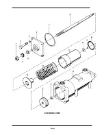
Page 2: ...Page 2 EXPLODED VIEW ...
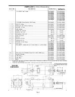
Page 3: ...See Kit 11 1 O RING 3 8 O D See Kit See Kit 12 1 WASHER 3 4 O D Piston R431002166 P 049804 00045 13A 1 STOP Piston For models P 066824 00000 P 063522 00000 P 057378 00000 R431004071 R431004072 R431004073 R431004074 R431004076 R431004077 R431004078 R431004079 R431004081 P 057384 00312 P 057384 00375 P 057384 00438 P 057384 00500 P 057384 00625 P 057384 00688 P 057384 00750 P 057384 00875 P 057384 0...

Page 4: ...zero stroke in the center position is Part Number R431004052 P 057378 00312 R431006294 P 063522 01000 P 066824 01000 R431004943 P 059211 00000 Pounds of force retracted stroke applied pressure psi x 2 2 inches 56 mm minus 18 psi x 2 4 inches 1 2 bar x 61 mm Pounds of force extended stroke applied pressure psi x 2 4 inches 61 mm minus 18 psi x 2 4 inches 1 2 bar x 61 mm For spring force at subseque...

Page 5: ...tenance periods should be scheduled in accordance with frequency of use and working conditions All AVENTICS products should provide a minimum of 1 000 000 cycles of maintenance free service when used and lubricated as recommended However these products should be visually inspected for defects and given an in system operating performance and leakage test once a year Where devices require a major re...

Page 6: ...1taria CANAD A L71tt TM www av e11tics cam ca i11fa ca a11e11tics cam Slv1 1 QQQ 49 16 rvlay 2QT4 Sul ie ctto c hange Printed in Urrited States AVEl iJTICS Carparatian This doc urne rrt as well as the data spec ific ations and atherinfurmation se tfurth in it are the ED Clusive prape rty atAVEl JTICS It may natb e repraduc ed orgive rr to third parties withoutits c onse nt ...

Reviews:

Related manuals for R431004052