background image

Model Number MD-WT-ADV-24 User Guide    

Page | 22                                                                         ©2018 Aventura Technologies, Inc. All rights reserved.  


F

REQUENCY 

A

DJUSTMENT


T

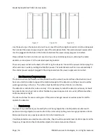
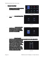
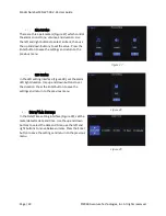
HE OPERATING FREQUENCY ADJUSTMENT

 (Figure 23) may be 

made as per site requirements. Use the left and right 

buttons to select Automatic or Manual adjustment of the 

frequency. Press the Enter button to enter into the 

desired sub-menu; press the power button to return to 

the previous menu.      


A

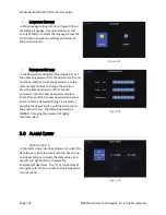
UTOMATIC ADJUSTMENT

 of the working frequency (Figure 

24), use left and right buttons to turn ON or OFF the 

automatic adjustment mode. Press the Enter button to 

save the settings and return to the previous menu.  


Note: If choosing automatic frequency adjustment, the 

walk-through metal detector will automatically detect 

the surrounding magnetic field each time it powers on 

and will set a working frequency which can function in 

the current environment; this will delay the metal 

detector’s boot time. The frequency automatic 

adjustment screen will close after the system finishes 

adjusting the working frequency. 


M

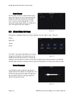
ANUAL ADJUSTMENT

 of the working frequency (Figure 

25) from frequency bands 0~99, for a total of 100 

frequency bands. Use the left and right buttons to 

increase or decrease the value by a factor of 10 and use 

the up and down buttons to increase or decrease the 

value by single digits. Press the Enter button to save the 

settings and return to the previous menu 


A

LARM 

D

EFINITION


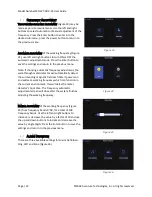
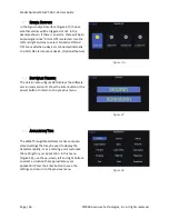
There are three available settings for Alarm Definition: 

Ring, LED and Zone (Figure 26) 

Figure 26


Figure 25


Figure 24 

Figure 23


Summary of Contents for MD-WT-ADV-24

Page 1: ...Walk Through Metal Detector User Manual MD WT ADV 24 Aventura Technologies 48 Mall Drive Commack NY USA 11725 Tel 1 631 3900 4000 Fax 1 631 434 7000...

Page 2: ...erations 12 2 1 Components of the System 12 2 2 Checkpoint layout 12 2 3 Parallel Operation 13 2 4 Assembling the Unit 14 2 5 Site Selection Considerations 16 2 6 Precautions 16 3 0 Controls Indicator...

Page 3: ...ge 2 2018 Aventura Technologies Inc All rights reserved 6 0 More Menu Settings 25 6 1 Display Brightness 25 6 2 Signal Outputs 26 6 3 Software Version 26 6 4 Application Type 26 7 0 Maintenance and re...

Page 4: ...are permitted at the work site The apparatus should not be operated by a person who may be sick or under the influence of drugs or alcohol Always connect the device to a grounded electrical outlet Be...

Page 5: ...detector in the same area be sure to choose different working frequencies see section 4 3 below 3 The installation location should avoid power lines and communication cables 4 The metal detector shall...

Page 6: ...he separation between the equipment and receiver Connect the equipment into an outlet on a circuit different from that to which the receiver is connected Consult the dealer or an experienced radio TV...

Page 7: ...of active service around the clock able to sound an alarm as needed screening large numbers of people efficiently to world class standards The sensitivity can be adjusted allowing detection of small m...

Page 8: ...y automatically checks the surrounding environment Graphical user operating interface with the large 7 inch color LCD screen Up to 99 999 alarms can be stored and reviewed based on calendar date and t...

Page 9: ...If set to 12 minutes the dormancy time will be 12X6 72 minutes Press the power on key to wake up the unit from dormancy SYSTEM CHECK System self checks for faults during the boot process TERMINOLOGY...

Page 10: ...The WTMD has many different operation frequencies and when the WTMD is calibrated at the installation site the lowest interference operation frequency should be chosen Detection Uniformity Uniform se...

Page 11: ...metal objects from different directions pass through the detector the differences in sensitivity are reduced due to the overlapping structures Each zone has significant differences in order to detect...

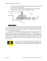
Page 12: ...ectrical Interference The distance between the electronic interference source and the receiving coil should be the greatest The recommended minimum distance should be 20 to 79 0 5m 2m However the actu...

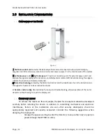
Page 13: ...Detection channel Formed by the Main Control Unit and the Side Panels this is the detection area through which persons to be screened must pass V Remote control unit Used primarily for setup and troub...

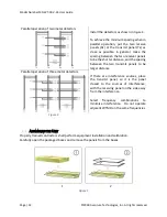
Page 14: ...stance between the WTMDs operation frequencies and sensitivities This equipment has different operation frequencies which can reduce the interference of adjacent detectors and can permit reliable para...

Page 15: ...e and the spacing between the two transmit panels to be larger distance If there are interference sources place the transmit panel so it is the panel closest to the sources of interference with the re...

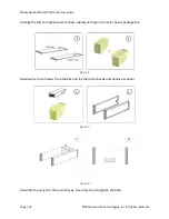
Page 16: ...eserved Arrange the left and right panels as shown below and open the main chassis package box Figure 6 Remove the main chassis from the box and lay the main chassis and panels as shown 5 6 Figure 7 7...

Page 17: ...he location where the detector will be placed should be smooth level and free of obstructions must be constructed to be able to support the combined weight of the detector and all persons who will be...

Page 18: ...Navigate through menu options Enter When the screen is in the normal operation mode pressing the Enter button will access the Options Menu When the screen is in Options Menu pressing the Enter button...

Page 19: ...ll access the Options Menu When the screen is in Options Menu pressing the Enter button will select the desired option Power When the screen is in the normal operation mode pressing the Power button f...

Page 20: ...sting the sensitivity in the programming screens 4 0 PROGRAMMING AND ADJUSTING SETTINGS LOGIN Press the Enter button to be prompted for the password see Figure 17 Use the and keys to increase decrease...

Page 21: ...ETTINGS AND RETURN TO THE PREVIOUS MENU The Zone screen FIGURE 21 SHOWS THE DEFAULT FOR A 6 ZONE CONFIGURATION AFTER SELF CALIBRATION USE THE UP AND DOWN BUTTONS TO HIGHLIGHT A SPECIFIC DETECTION ZONE...

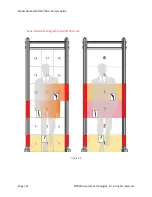
Page 22: ...Model Number MD WT ADV 24 User Guide Page 21 2018 Aventura Technologies Inc All rights reserved Zone schematic diagram for 6 and 18 zones Figure 22...

Page 23: ...ment the walk through metal detector will automatically detect the surrounding magnetic field each time it powers on and will set a working frequency which can function in the current environment this...

Page 24: ...return to the previous menu LED SETTING In the LED setting interface Figure 28 set the alarm LED light duration Use up and down buttons to set the duration Press the Enter button to save the settings...

Page 25: ...tons to change the position Press the Enter button to confirm the old password input the new password and press Enter then confirm the new password and press Enter After the password change is success...

Page 26: ...More screen These are Display Signal Out Version No ID The More menu Figure 34 allows you to set the display screen brightness the signal output and application spot standard selection and view the so...

Page 27: ...alarm output device Optional feature SOFTWARE VERSION The Version menu Figure 38 displays the software version and version ID Press the Enter button or the power button to return to the previous menu...

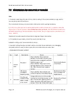
Page 28: ...sensitivity to low Suitable for all large and small entertainment venues 4 Automatic setting frequency normally needs to close after the metal detector door debugging completed which can save the time...

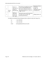
Page 29: ...on the infrared component it may also trigger an alarm Replace the infrared component Change the installation location to avoid the sun 5 There s no alarm when people pass with metals Normally it is b...

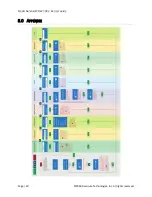
Page 30: ...Model Number MD WT ADV 24 User Guide Page 29 2018 Aventura Technologies Inc All rights reserved 8 0 APPENDIX...

Reviews: