background image

www.avenview.com

Page 11

1

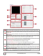
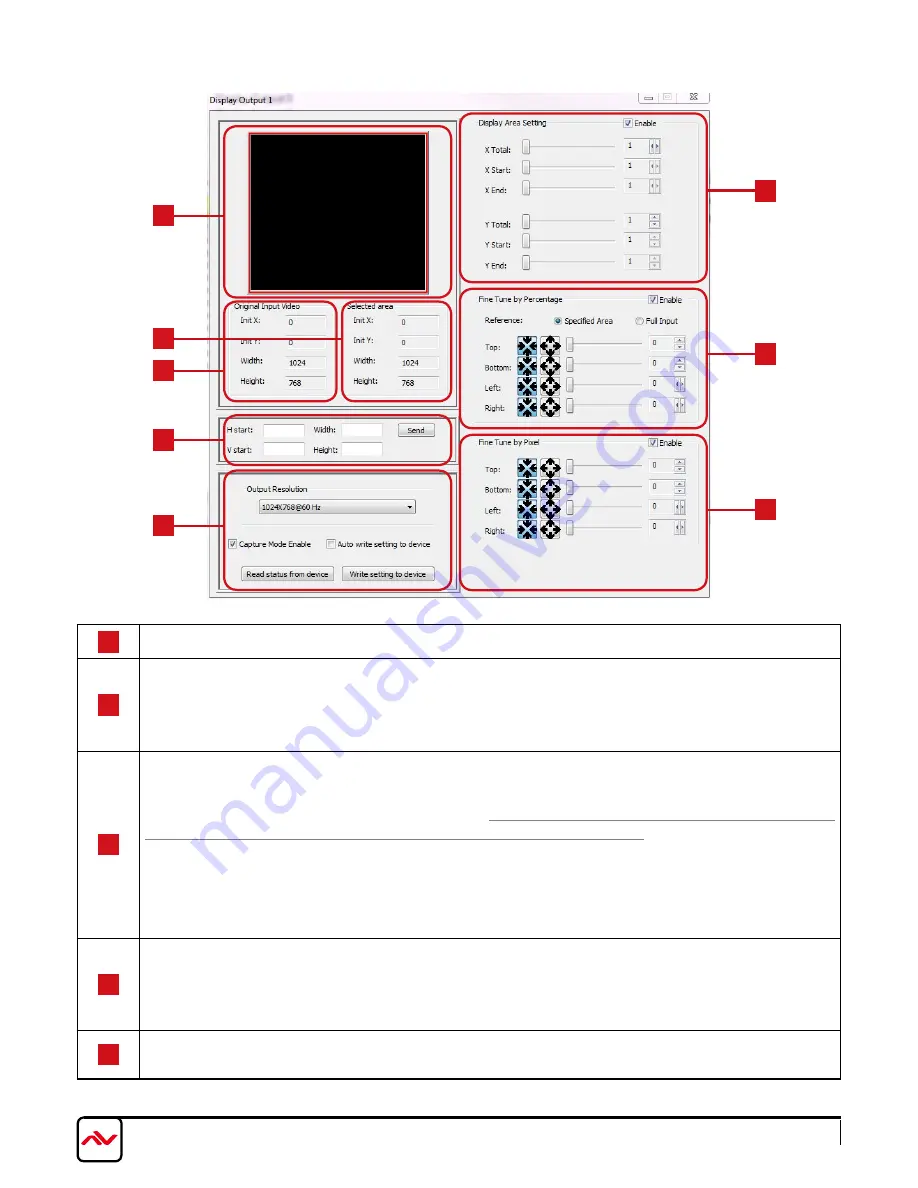
This area demonstrates the resulting selection of the Input video to be display for the selected Output Channel.

2

“Original Input Video”

 shows the resolution information of the Input Video to each Output Channel. It varies up 

the Input Video

“Selected Area”

 shows the information of the selected area to be displayed. The numbers will vary according to 

different settings.

3

“Output Resolution”

 This section can set the output resolution for individual output channel. Notice that each 

display can run at different resolutions to adapt more situations coming from different panels

“Capture Mode Enable”

 will enable parameters effective. 

IF USERS DISABLED THIS SELECTION, EACH OUTPUT 

CHANNEL WILL DISPLAy SIMPLy THE FULL DISPLAy OF THE INPUT SOURCE.

“Auto Apply Settings”

 will automatically load the new settings into processor.

Clicking on 

“Read status from device”

 will show the current settings that Output card is configured.

Clicking on 

“Write Settings to device”

 will load the user parameters into the video processor.

4

User can directly configure each text field to set the area to display on the screen.

Remark: For each display, users can define which area of the input video is to be displayed. Please define the upper-
left (V Start, H Start) and its length (V length, H length) corners for each display channel. User can Press 

“SEND”


to confirm custom defined settings.

5

Define 

X Total, Y Total, 

this


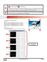
section creates the user defined configuration for the Videowall setup Ex. 2x2, 3x3,1x4. 

Users can view the resulting captured area to the Input video in Window to the left.

1

4

5

5

2

2

3

3

Summary of Contents for DVI-VIDEOWALL-9X

Page 1: ...nties with respect to the accuracy or completeness of the contents of this publication and reserves the right to make changes to specifications and product descriptions at any time without notice No l...

Page 2: ...Military Residential Medical Aviation Education Industrial Corporate House Of Worship www avenview com Product Application Market Sectors...

Page 3: ...2 BEFORE INSTALLATION 6 3 PANEL DESCRIPTION 6 4 HARDWARE CONECTION 7 4 1 Unpacking 7 4 2 Placement 7 4 3 System Requirements 7 4 4 System Connection 7 5 SOFTWARE OPERATION 8 6 SOFTWARE TOOLBAR 9 Exam...

Page 4: ...isplay Video Wall Processor has been tested for conformity to safety regulations and requirements and has been certified for international use However like all electronic equipment s the DVI VIDEOWALL...

Page 5: ...hority to operate this equipment Warning symbols Description ONLY USE THE PROVIDED POWER CABLE OR POWER ADAPTER SUPPLIED DO NOT TAMPER WITH THE ELECTRICAL PARTS THIS MAY RESULT IN ELECTRICAL SHOCK OR...

Page 6: ...nput sources to match the native resolution of monitors flat panel displays projectors as well as user selectable output settings up to WUXGA 1920x1200 The DVI VIDEOWALL 9X sends the resulting mixed v...

Page 7: ...www avenview com Page 4...
Page 8: ...nts 1 DVI VIDEOWALL 9X X 1 2 Y CABLE S VIDEO TO S VIDEO CVBS X1 USER S MANUAL X 1 INSTALLATION SOFTWARE CD X 1 DVI TO DVI CABLE DVI TO DVI VGA BREAKOUT CABLE X 1 COMPONENT TO VGA ADAPTER X 1 DVI TO VG...

Page 9: ...er Switch AC 100 120V Power On Off Switch 2 RS 232 Device Control communication port Via RS 232 Cable or USB to RS 232 Supplied 3 Dip Switch UP Position Normal operation mode Down Position Firmware up...

Page 10: ...ws then insert the Installation CD provided and have Windows search for drivers you may need to download latest drivers from Prolific s website if you are using Windows Vista or Windows 7 or later 4 4...

Page 11: ...L 9X The serial connection is not well established Please ensure that the Prolific drivers are properly installed and all cables are securely connected Check device manager and ensure that RS 232 to U...

Page 12: ...automatically adjusted It only works when the source is Analog and the mode is Full Screen 5 Apply Display settings This applies the changes selected by the user Button Name Description Function Stat...

Page 13: ...ntly setup to display any area of the input video Each output can be with different output resolutions to adapt different combinations of monitors or projectors To select each individual Output to set...

Page 14: ...UT CHANNEL WILL DISPLAY SIMPLY THE FULL DISPLAY OF THE INPUT SOURCE Auto Apply Settings will automatically load the new settings into processor Clicking on Read status from device will show the curren...

Page 15: ...approach to adjust the position and area of the Output channel The idea behind this section is the same as Fine Tune by Percentage The difference is that the adjustment is based on Pixels Users can t...

Page 16: ...ew com Page 13 The Avenview DVI VIDEOWALL 9X can be cascaded with as many as 255 DVI VIDEOWALL 9X devices Example shows another model 4 Port Videowall but same setup can be accomplished with 9 Port 9...

Page 17: ...1280x960 60Hz VESA 640x480 60Hz VESA 1280x960 85Hz MAC 640x480 67Hz VESA 1280x1024 60Hz VESA 640x480 72Hz HP 1280x1024 60Hz VESA 640x480 75Hz IBM 1280x1024 67Hz VESA 640x480 85Hz HP 1280x1024 72Hz VES...

Page 18: ...Input Source wait 10 20 seconds After the resolution is changed the selection of Input and the Display layout mode will return to default Adjust the Input source and Display Layout Mode to your requir...

Page 19: ...nal 5 Volts peak to peak TTL ESD Protection Human body model 15kV air gap discharge 8kV contact discharge Core chipset 8kV Input Connectors DVI x 1 S Video x 1 RS232 x 1 RS485 x 1 Output Connectors DV...

Page 20: ...punitive incidental or consequential damages in connection with the furnishing performance or use of the Avenview hardware software or other products and documentation provided herein Avenview Inc res...

Reviews: