background image


Page|51


www.avenview.com 


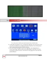
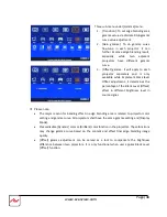
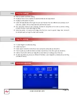
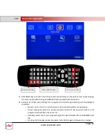
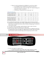
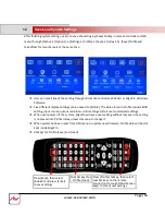
Adjust the correct location for black level uplift by [Corner] menu. 


When user adjust the location of the control points, user will see the change of color uplift 
position. If the projector is at RH side, please adjust LH control points to RH side till to the edge 
of the light leakage region. This region starts from original projection area before geometry 
alignment. It is not the same as overlap area. 


T

he maximum adjustment range is +_900 pixels in vertical direction and +_1200 pixels in 

horizontal direction. 


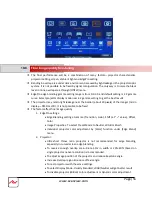
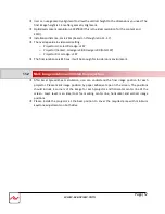
After this step, user will see clearly the black level uplift region and back to Offset color settings 
to let the color in uplift region is similar to light leakage area. 


Projector display imager, such as DMD, LCD and LCOS, will have some image borders due to 
active display window is not at full range of the imager. In dark environment, viewer may see 
this kind of light leakage in image borders. It is outside active display area and can’t be fixed. 


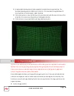
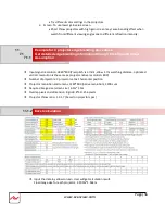
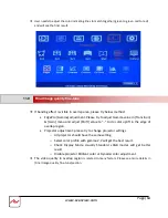
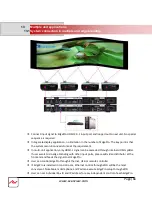
Below is to show color adjustment in black level uplift areas through above method. It can show 
different colors with different shape of the borders. Maximum adjusting area is nine. 


10.4.2 

 [Corner]


Summary of Contents for MLT-EDGEPRO-2X2E

Page 1: ...VIDEOWALLS VIDEO PROCESSORS VIDEO MATRIX SWITCHES EXTENDERSSPLITTERSWIRELESS CABLES ACCESSORIES Control Your Video 2X2 4K DUAL CHANNEL CURVED SCREEN EDGE BLENDER User Guide Model MLT EDGEPRO 2X2E...

Page 2: ...racy or completeness of the contents of this publication and reserves the right to make changes to specifications and product descriptions at any time without notice No license whether express implied...

Page 3: ...6 7 How to use IR Remote Control 19 6 8 Full screen and native aspect ratio 20 6 9 Image rotation and flip 21 6 10 Color adjustment 21 6 10 1 Global color adjustment Picture 6 10 2 Pre set Color Temp...

Page 4: ...ift image position without changing image size 45 10 10 Edge Blend settings 45 10 1 Edge selection location and set edge blending value 46 10 2 Shift shift Edge Blend position and execute Edge Mask 47...

Page 5: ...ent displayed in each projector 76 15 5 Complete system aspect ratio adjustment 77 16 16 Miscellaneous settings 78 16 1 Helpful tips for edge blending 78 16 2 System structure and control 79 16 2 1 Sy...

Page 6: ...CTIONS The HDMLT C5SP 4 and HDMLT C5SP 8 HDMI Splitter 1x4 1x8 Over CAT5E CAT6 50m has been tested for conformance to safety regulations and requirements and has been certified for international use H...

Page 7: ...modifications made to this equipment may void the user s authority to operate this equipment Warning symbols Description ONLY USE THE PROVIDED POWER CABLE OR POWER ADAPTER SUPPLIED DO NOT TAMPER WITH...

Page 8: ...Linearity Grid Line Adjustment are new function in geometry alignment Separate RGB gamma correction for edge blending region color fine tune individual color correction for each output color uniformit...

Page 9: ...d flip 3 Each unit controls dual projectors and can be cascaded to control unlimited number of projectors 4 Integrated with full function IR remote controller Manual geometry alignment up to 9 5 grid...

Page 10: ...up to 15x15 matrix display from single signal input source F Image rotation and flip 1 Image 90 270 degrees rotation flip under 4k 30Hz input Image 0 180 degrees rotation and flip supports up to 4k 6...

Page 11: ...AC DC Power supply systems Provide DC 12V 1A output for signal extender while using AC 16 Dimension and weight 440x190x45mm 2 2kg Body only 4 Package Contents 1 The EdgePro Dual Channel Video Wall Co...

Page 12: ...ARD INPUT TIMINGS Settings Save SETTINGS BACKUP AND SAVE GRID CONTROL POINTS 17 X17 GRID PATTERN Selectable grid pattern size from 8 100 pixels in H V direction Default is 32 32 pixels Selectable grid...

Page 13: ...ase select source for CH 1 then second source for CH 2 User can t select two different HDMI input sources and display separately in two projectors 6 2 Connecting the outputs If the system uses only tw...

Page 14: ...able LED lights up after proper input output signals are active 6 3 Input Output selection LED Indicators If Power SW is on LED will light up If Input Source is detected LED will light If Output proje...

Page 15: ...input port for each output channel The output resolution selection will apply to both output channels at the same time Default output resolution for all channels is 1080p The output resolution should...

Page 16: ...lity HDMI cable and signal source will affect the connection distance and may cause signal noise or show intermittent image To ensure all cables are connected correctly it is recommended to use lockin...

Page 17: ...ood cable or lower source resolution can connect more units User can also add HDMI splitter at the front end to increase daisy chain connection number for large scale video display If loop out port is...

Page 18: ...et Crossover UTP cable can be used for direct connection between PC and EdgePro User needs to set PC TCP IPv4 with the same domain as EdgePro for instance to set IP address at 192 168 0 105 and subnet...

Page 19: ...EdgePro through WiFi via PC iPad or mobile phone If web server function is required please contact us for further details IR remote controller has full functions for the operation of EdgePro IR receiv...

Page 20: ...power off by remote controller please power on by Profile Load shortcut key Channel selection HDMI2 0 2 input port HDMI2 0 1 input port Work with other function keys to execute function to all channel...

Page 21: ...When the image is rotated or flipped the OSD will still keep at original direction without change The direction for Video Wall settings will follow the image after rotated or flipped Image 90 270 degr...

Page 22: ...uration Sharpness o When input is RGB 4 4 4 Brightness Contrast Sharpness Color under Image Properties menu can change preset color temperature and discrete RGB color in each channel Preset Mode Neutr...

Page 23: ...flashing LED on front panel after press 85x number keys It means the OSD menu in EdgePro with flash LED is locked and will not be controlled by remote controller OSD Lock Unlock When continuously pre...

Page 24: ...ee Run mode when EdgePro changes input source or timing the output will be still running without losing any signal The projector will not search the input source again There will be no loss signal whe...

Page 25: ...s Therefore the final result will be around 7 grids 224 pixels to 13 grids 416 pixels for XGA projector and 12 grids 384 pixels 24 grids 768 pixels for 1080p WUXGA projectors If the projector has accu...

Page 26: ...overlap area to increase the control points in overlap region for more accurate alignment between adjacent projectors Below figure is an example for 9x5 Curved alignment in 1024 resolution 25 overlap...

Page 27: ...resolution 1920 1080 1280 800 1024 768 Min adjusting flexibility 256 480 704 320 480 640 256 384 512 Max adjusting flexibility 352 608 832 224 256 384 416 544 576 192 320 448 576 AVENVIEW can provide...

Page 28: ...higher than the required one User can draw the vertical height to required dimensions through geometry alignment The vertical adjustment range in each edge is 600 pixels o Optimized content resolutio...

Page 29: ...llation height install the projector at a position with minimum keystone at both vertical edges Based on the calculation data user can easily determine the image location for each projector Using lase...

Page 30: ...ntal and vertical line and make sure each projector can cover correct display Please reset all projectors to factory default settings Set to ceiling mount if necessary Disable below items Auto keyston...

Page 31: ...erent grid size from 8 100 pixels The show up time can be determined by Options Accessibility Menu Time Out If set at 0 the OSD and pattern will show up all the time unless input timing is changed or...

Page 32: ...to meet high end simulation system geometry alignment requirements The grid size in both horizontal and vertical directions is from 8 to 100 pixels with 1 pixel increment H V grid size will be the sam...

Page 33: ...et and apply an overlap pixel in the Spread Sheet to get a near integrate number in Video Wall Overlap value then select the grid size to match this overlap pixel In low resolution projector with low...

Page 34: ...hould execute geometry video wall setting and edge blending setting separately Use Pattern CH 1 CH 2 selection keys to show grid patterns in all projectors Press Pattern key again will change grid col...

Page 35: ...cal borders without keystone Measure the image size in each projector to reduce the size of the larger image at top edge through 2x2 alignment and let both projectors have similar grid size and number...

Page 36: ...rids near center overlap region with good stacking It allows small image shift in both sides of the overlap region because edge blending will reduce the effect for the mis alignment in side borders Us...

Page 37: ...rid line for the adjustment Each control point can shift the image in both horizontal and vertical directions When user projects the image to curve screen using projector the image grid size will cont...

Page 38: ...n apply Corner Wall function all the other geometric alignment function will be disabled User can only execute geometry alignment through 8 points of Corner Wall adjustment 4 corner control points can...

Page 39: ...0 pixels and the location adjusting range is _900 pixels The image will keep the same grid size scaling factor automatically User can t use ultra short throw ratio projector for corner wall applicatio...

Page 40: ...d to connect the output to the input port of the channel for Corner Wall alignment Then user can execute curve alignment and Corner Wall adjustment at the same time If only only one EdgePro is used us...

Page 41: ...ng to UserMap when user clicks any UserMap menu or select one UserMap without storing any Windows data user may not see any image on the screen Under this condition please press 2x2 geometry alignment...

Page 42: ...ge to each EdgePro display device in the matrix The overlap pixel between two images can be adjusted pixel by pixel The maximum video wall can be up to 15x15 matrix display Press Menu Keypad on Front...

Page 43: ...om single input source For 3 projectors at horizontal position Horizontal Zoom 3 Vertical zoom 1 For 3x3 displays 9 projectors Horizontal Zoom 3 Vertical Zoom 3 Use Pan to determine the location of ea...

Page 44: ...range is _1200 Pixels In multiple projector applications if the overlap region has different size due to installation position limitation the overlap value may be different between projectors However...

Page 45: ...nding To let the image has the same grid size same scaling factor in both horizontal and vertical directions To let images overlapped together in horizontal lines and vertical lines Sub menu under Edg...

Page 46: ...when set edge blending pixels User needs to adjust the color indicating lines to match together green to green red to red There is no need to calculate the overlapped pixels For 3 projector edge blen...

Page 47: ...olor in edge blending area It can execute Edge Mask on the edges in non overlapped region Different projectors may have different gamma curve Different Display mode in the same projector will also hav...

Page 48: ...determines the percentage of the Black Level Offset effect in different brightness level in source signal Please note The major reason for banding effect in edge blending area is related to projector...

Page 49: ...If the ambient light is dark audience will see grey region in Edge Blending area It is due to light leakage from projector optical system and can t be fixed by signal processing Low contrast ratio pro...

Page 50: ...100 each If user executes more complicated edge blending such as 4 projectors at 2x2 location The maximum areas for black level uplift may increase up to 9 locations Under this condition user needs t...

Page 51: ...tion and _1200 pixels in horizontal direction After this step user will see clearly the black level uplift region and back to Offset color settings to let the color in uplift region is similar to ligh...

Page 52: ...in each projector Gain is to change the color slope and will see significant in brighter color Offset is to add value in all level of brightness 0 225 User can see more effect in darker color When ap...

Page 53: ...r geometry alignment Edge Mask There are 8 control points for edge mask When user moves the position for each control point it will result various edge mask pattern The maximum position adjustment for...

Page 54: ...d simulation system geometry alignment requirements The grid size in both horizontal and vertical directions is from 8 to 100 pixels with 1 pixel increment H V grid size will be the same User can sele...

Page 55: ...It is not possible to be fixed The factors affect final image quality 1 EdgePro settings Edge Blending settings Gamma Transition Gain Shift at value Offset Color Image Properties To select Preset Mod...

Page 56: ...projector native resolution 800 Number of projectors 3 projectors at 3x1 horizontal position Projector resolution and lumens 1280 800 native resolution 3200 Lum Required image size screen size 6 5m 1...

Page 57: ...Projector RH LH edge 197 The final luminance is 819 Lux It will be enough for inside room environment After Excel Spread Sheet calculation user can understand the final image position for each project...

Page 58: ...lease install two IR extender at different location for easy individual access by remote controller Each EdgePro needs one IR extender User can setup EdgePro through Ethernet Please change IP address...

Page 59: ...ement edge blending Install projectors at a place with image size that can cover required image area and with minimized keystone to get the best video quality To reset EdgePro to default setting Selec...

Page 60: ...nt Output resolution settings in different EdgePro are not the same Projector aspect ratio setting is different or not set at full screen display EdgePro is set at Original AR under the menu of Image...

Page 61: ...ing area between two adjacent projectors should be aligned together After the above processes if the grid pattern in edge blending area still can t stack together user can reduce overlapped grids to c...

Page 62: ...ng with two EdgePro cascaded o Zoom set to H 3 V 1 in all channels Each channel should be set separately o Pan LH projector 1st H 1 Center projector 2nd H 2 RH projector 3rd H 3 All projector Vertical...

Page 63: ...all have the same value same cropping range The difference shall not be over 2 pixels If user still sees some blurred image in edge blending area please increase or decrease Overlap value in Video Wal...

Page 64: ...to to do color uplift in the edge of overlap region Projector adjustment please try to change projector settings o All projector should have the same setting o Select color profile with gamma 2 2 wil...

Page 65: ...de EDID setting input source output resolution color settings and all user customized settings When user power off the system EdgePro will save user setting without loss even the setting is not saved...

Page 66: ...HDMI splitter If user wants to do edge blending with other input ports please add video distributor at the front end and feeds the signal to all EdgePro User can control EdgePro through Ethernet USB...

Page 67: ...calculation To apply 1080p or 4k signal is recommended After system setup user can use any input resolution Press INFO hotkey to check if the final in out timings are the same as expected Usually one...

Page 68: ...nal sources shall be handles through below methods To set Overlap image through PC display card In this case the overlap cropping issue in this section will be handled by PC To cut the content with sa...

Page 69: ...be operated Press 850 all the box OSD will be unlocked and can be operated through remote controller at the same time User can connect all EdgePro in one Ethernet Router WiFi Router or switch hub thro...

Page 70: ...go through Ethernet router LAN port WiFi Router or Crossover Cab 5 6 cable User can set each EdgePro with different static IP address in the same domain then open Google Chrome or Microsoft Explorer b...

Page 71: ...restore or copy to other units Firmware and MCU code update can be executed through EdgePro Windows Software User can control multiple units at the same time through different IP address User can use...

Page 72: ...jector is enough W2 require two projectors with edge blending to cover the space W3 one projector is enough Floor 2 3 projectors is required Need to let all projectors with the same scaling factor to...

Page 73: ...Pixel based on this resolution If we set 320 overlap pixels the overlap value in video wall is 86 pixels Under this condition the image cropped for PJ2 should be in the range from coordinate 914 to 1...

Page 74: ...t will be more convenient for user to connect with all kinds of conventional signals without the need to rotate the image in advance When apply portrait edge blending the Excel Spread Sheet calculatio...

Page 75: ...user needs to reset all settings select the input sources for discrete display and implement geometry alignment to separate the images apart from two projectors without overlap Save the setting to Ind...

Page 76: ...d Edge Blend to default value User need to use geometry alignment to let the images in projectors apart from each other If necessary user can use Overlap function under Video Wall to adjust image aspe...

Page 77: ...Video Wall Zoom is set to H 1 V 1 1800 pixels edge shift in RH and LH edges is only available under input signal up to 4k 2k 30Hz Top Edge and Bottom edge are still functional when the input is 4k 60...

Page 78: ...o 4k 2k input signal the adjustment value should be 2000 pixels However due to the maximum adjustment value is only 1800 pixels the final image will follow 1800 pixels but not 2000 pixels for 4k input...

Page 79: ...ler RS232 and Ethernet are available for system control They can be used simultaneously to provide the most flexibility in system control HDMI 1 HDMI 2 input signals will go through the same HDMI swit...

Page 80: ...l source The purposes for EDID setting are as follows The EdgePro can support big range of input signal timing from XGA up to 4k 2k 60Hz In order to get the best video performance user needs to select...

Page 81: ...t DVI output format for normal display in some devices User can also set EDID manually The range for customized EDID will be from 1024x768 to 3840x2400 Horizontal resolution is in a step of 8 pixels a...

Page 82: ...user can control signal source to execute entire system on off control When no signal input the system will show blue color background with Power Saving Mode message on the screen User can change back...

Page 83: ...ss Menu key for 5 seconds or press 850 number keys in remote controller to disable OSD locked Check the HDMI cable quality and make sure all cables are inserted correctly 4k 60 signal requires high sp...

Page 84: ...interlaced 1080i and the image is rotated or flipped then the channel will have no 3D Motion adaptive de interlaced processing function If user applies static image source the output video will have...

Page 85: ...otation can only be achieved under 4k 2k 30Hz input resolution When the input source is 4 4 4 PC graphics signal only Brightness Contrast and Sharpness three items under Picture menu can be executed I...

Page 86: ...iew and purchaser are responsible for freight charges and brokerages when shipping the product s to the receiver NOT COVERED BY THIS WARRANTY This warranty does not apply to any non Avenview branded p...

Page 87: ...loss or interruption of business loss of anticipatory profits or for punitive incidental or consequential damages in connection with the furnishing performance or use of the Avenview hardware software...

Reviews: