4
ENGLISH
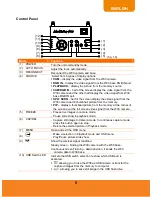
B a s e
(7)
(6)
(5)
(1)
(2)
(4)
(3)
(fig. 1.5)
Name
Function
(1) Antenna
Send and receive data signal to and from W30 camera and base.
(2) Rear Panel
Connections for computer, RGB/DVI-I/RCA external display device, and
RS-232 communication port.
(3) Control Panel
Easy access to various functions.
(4) IR Sensor
Receive remote control commands.
(5) Right Panel
Switches for USB and output display selection, and SD card slot
(6) Left Panel
Connection for power and output resolution selection switch.
(7) LED Light
Indicate the display output selection, USB switch selection, and wireless
signal condition.
Rear Panel
(1)
(2)
(4)
(3)
(fig. 1.6)
Name
Function
(1) DVI-I OUT
Connect the W30 base to any display device with DVI cable.
(2) RGB OUT
Connect the W30 base to any display device with RGB cable.
(3) RGB IN
Input the signal from a computer or other sources and pass it
through to the RGB OUT port only. Connect this port to the
RGB/VGA output port of a computer.


