background image

v

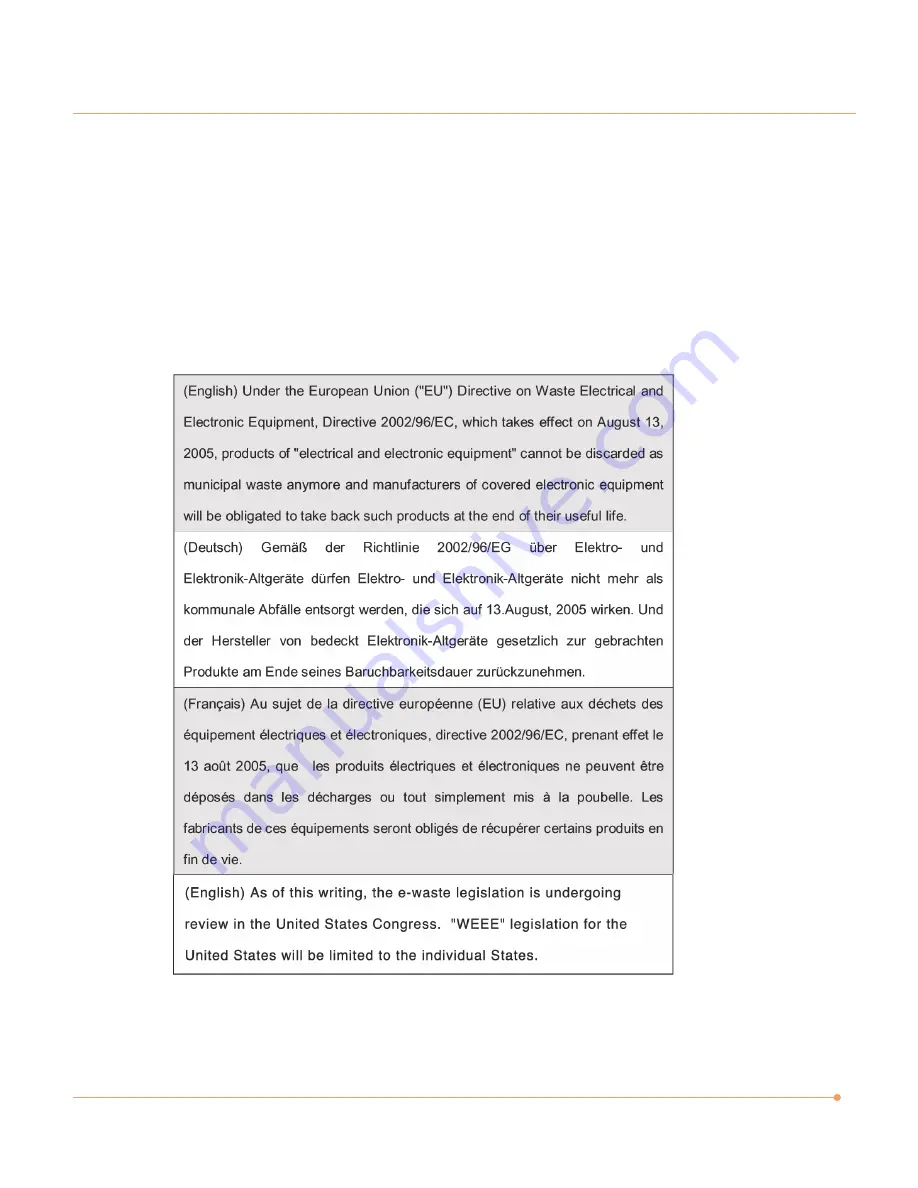
WEEE Statement

12. Do not leave the equipment in an unconditioned environment with a storage temperature of

60°C (140°F) or above, which may damage the equipment.

13. To prevent explosion caused by improper battery replacement, use the same or equivalent

type of battery recommended by the manufacturer only.

Summary of Contents for D1002

Page 1: ...TM All In One PC User s Guide ...

Page 2: ...ar installation If this equipment does cause harmful interference to radio or television reception which can be determined by turning the equipment off and on the user is encouraged to try to correct the interference by one or more of the following measures Reorient or relocate the receiving antenna Increase the separation between the equipment and receiver Connect the equipment into an outlet on ...

Page 3: ...timeters between the radiator and your body This transmitter must not be co located or operated in conjunction with any other antenna or transmitter FCC Conditions This device complies with part 15 of the FCC Rules Operation is subject to the following two conditions 1 This device may not cause harmful interference 2 This device must accept any interference received including interference that may...

Page 4: ...nce In case of any trouble with this model please contact your nearest AUTHORIZED service station To prevent direct exposure to the laser beam do not try to open the enclosure Battery Notice Ethernet Notice This equipment is indoor use and all the communication wirings are limited to inside of the building CAUTION RISK OF EXPLOSION IF BATTERY IS REPLACED BY AN INCORRECT TYPE DISPOSE OF USED BATTER...

Page 5: ...ating Do not cover the openings 6 Make sure that the power voltage is within its safety range and has been adjusted properly to the value of 100 240V before connecting the equipment to the power inlet 7 Place the power cord in a way that people are unlikely to step on it Do not place anything on the power cord 8 Always unplug the power cord before inserting any add on card or module 9 All cautions...

Page 6: ...an unconditioned environment with a storage temperature of 60 C 140 F or above which may damage the equipment 13 To prevent explosion caused by improper battery replacement use the same or equivalent type of battery recommended by the manufacturer only ...

Page 7: ...vi ...

Page 8: ...vii ...

Page 9: ...nd Remote Control 4 Adjusting the Brightness of the Monitor 8 Adjusting the Speaker Volume 9 Connecting Your Multi Channel Speakers 10 Using the Optical Drive 12 Connect to the Internet 15 Using Your Webcam 16 Using the Wireless LAN 18 Using the Multi Card Reader 20 Watching TV 21 System SETUP 25 Expanding the Main Memory 32 ...

Page 10: ...ystem portability and results in less clutter Everything s Included The Averatec All In One PC includes everything necessary to be immediately productive An industry leading 22 widescreen LCD monitor coupled with an advanced Intel Pentium processor to handle all your entertainment and productivity applications Additionally the Averatec All In One PC comes with the following features A huge super f...

Page 11: ...rning On and Shutting Off Turning off Turning on Press the power button on the right side of the PC Case 1 Click Start to turn off computer Click start and select Shut Down Turn off computer screen displays ...

Page 12: ...turned off If the system is operating abnormally you can reboot the PC by holding down the Power button until the PC turns off Then press the Power button again to boot back up Case 3 Power saving mode Saves your session and puts the computer in a lower power state so that you can quickly resume working ...

Page 13: ...will need to install the batteries 1 Place the wireless keyboard mouse and remote control upside down and remove the battery covers from them 2 Insert the batteries into the wireless devices Be sure to install the battery with the correct polarity 3 Replace the cover of the wireless devices Wireless keyboard Wireless mouse Remote control ...

Page 14: ... computer Turn on the computer by pressing the power button on the right side then check each wireless device works properly with your computer 4 Set the ON OFF switch to the ON position on the bottom side of the mouse ...

Page 15: ... reason follow these instructions 1 Press the connect button on the right side of the computer with a tip of a pencil or paperclip for 1 to 2 seconds 2 Press the connect button on the bottom of the wireless keyboard for 2 to 5 seconds Wireless keyboard 1 Turn on the wireless mouse 2 Press the connect button on the right side of the computer with a tip of a pencil or paperclip for 1 to 2 seconds 3 ...

Page 16: ...the connect button on the right side of the computer with a tip of a pencil or paperclip for 1 to 2 seconds 2 Press the Back and More buttons simultaneously for 3 to 5 seconds on the remote control Remote control ...

Page 17: ...r darker display 75 Adjusting the Brightness of the Monitor You can adjust the brightness by clicking the brightness control button on the right side of the LCD panel There are 4 levels of LCD brightness adjustment available Each press of the brightness control button will cycle through each level ...

Page 18: ...me level and the bottom volume button to decrease the volume level Mute button To mute the speaker sound press it once to enable mute and press it again to disable mute Volumebutton Up Volumebutton Down Speaker Mutebutton The Speaker volume level can be adjusted easily with the button located on the bottom side of the LCD panel ...

Page 19: ...he speakers to SPDIF jack Multi channel speakers optional Multi channel speakers optional or Note Connecting the speakers will cause a window to appear confirming detection of the device When configured for 5 1 audio speaker setup the MICROPHONE LINE IN and LINE OUT all function as INPUT JACKS AV Receiver optional ...

Page 20: ...ek HD Audio Manager icon Adjusting volume The Averatec All In One PC has built in speakers on the front and back of the system You can adjust the volume by clicking the volume adjustment buttons located on the right side of the LCD panel and or by using the volume control feature in Windows Vista 2 Click Speaker Configuration tab and click 5 1 speaker 3 Click OK button ...

Page 21: ...der Slot loading CD drive 1 Insert CD DVD With the system powered on insert a CD DVD into the CD DVD drive Slide the CD DVD into the system with the disc label facing up If the label side is facing down the CD will be ejected automatically after two minutes 2 Eject CD DVD Press the Eject CD DVD button to eject the CD 1 2 12 ...

Page 22: ...D DVD drive 2 Insert CD DVD Insert CD DVD in the CD DVD drive and place CD DVD label side front Press the CD DVD Drive 3 Eject CD DVD Press the Eject button of the CD DVD drive on the right side of the Averatec All In One PC You can then remove the CD DVD 1 2 ...

Page 23: ... you can not eject a CD DVD from the drive click Start choose Computer right click on the CD DVD drive that the CD DVD is in and choose Eject in the popup menu Make sure CD DVD is not inserted upside down CD label side facing toward front of PC Labels on CD DVD may cause noise when CD DVD drive is working Remove labels on CD DVD for safe use CD 120mm ...

Page 24: ...ure below 2 Configure the communication settings for the system based on your communication environment When connecting to the Internet via an internet service provider contact the service provider for more information on required communication settings 3 Launch Internet Explorer or other communication software Connect to the Internet ...

Page 25: ...and the system of the person you want to chat with must have a web camera or a CCD camera installed You also need to download and install a messenger program The screen that you will see varies depending on the type of the messenger program you re using 1 Run the messenger program to register your user email address When the messenger is ready double click on the Windows Messenger icon Select Sign...

Page 26: ...17 2 Right click on your chat partner and then select Show your webcam as illustrated below 3 Now you re ready to start chatting ...

Page 27: ...figuration features to configure the system You can also use the program that comes with the wireless LAN card to configure the network 1 Right click on the Wireless Network icon on the status bar and then select Connect to a network 2 If there is an AP enabled environment a list of available APs will appear Click the item you want to connect to and click Connect Using the Wireless LAN ...

Page 28: ... its shape Select the right items for your environment and click Close 3 A window will appear displaying Connecting to xxxxx Where XXXXX is the name of your router AP If a Security key or password is set up a window will appear where you can enter the security key or password Enter the security key or password and click Connect The window will not appear if no security key or password is set up ...

Page 29: ... are not inserted completely the tip of the cards will remain out of the slot Insert cards with label side facing toward the back of the PC Removing multi media card Grip the tip of the card and take it out from the slot Do not remove the card while you are using it as you could corrupt the contents Using the Multi Card Reader Note Click the Start menu and select Computer On the Computer screen ri...

Page 30: ...an external antenna cable directly to the system to watch TV 1 Connect Antenna cable to TV tuner 2 Click Start and the select Windows Media Center Watching TV Note When the Start screen appears on your first use select Quick Installation and then click OK ...

Page 31: ...e TV follow the instructions on the screens 4 When the TV Signal screen appears click Next Note If you haven t already done so connect to the Internet 5 When the Confirm Your Region screen appears choose your region and then click Next ...

Page 32: ...pears select how you would like to proceed and then click Next Choosing Configure my TV signal automatically is recommended here 7 If TV signals are configured normally select Yes and then click Next If necessary you can manually configure TV signals ...

Page 33: ...e screen appears follow the online instructions to install the program The installation method varies depending on the user environment 9 In the TV Movies menu move to live TV and click on it Now you are set to watch TV ...

Page 34: ...ystem Setup screen BIOS Action Keys Leaves a sub menu to return to the previous menu OR exits the BIOS setup while saving changes Shows the Sub Menu ESC Exit Enter Select Function Key Command Description Shows the Help Screen F1 General Help Saves changes and reboots the computer F10 Save and Exit Selects the next field Tab Select a field Selects the next item Select an item value Selects the next...

Page 35: ...26 BIOS Setup Menu Standard CMOS Setup Menu Sets most standard specifications for the system such as the time date HDD settings and FDD size and capacity ...

Page 36: ...Advanced Setup Menu Sets up key items related to the system s performance and options about booting Advanced Chipset Setup Menu Consists of DRAM Frequency Configure DRAM Timing by SPD and Share Memory Size ...

Page 37: ...8 Integrated Peripherals Menu Sets up options about the chipset built into the main board Sets up options about the internal speaker Power Management Setup Menu Sets up options for managing system power ...

Page 38: ...29 PCI PnP Setup Menu PC Health Status Menu ...

Page 39: ...ress to go to the Supervisor Password menu and then press Enter 2 Go to Change Supervisor Password and then press Enter Frequency Voltage Control Menu Supervisor User Password Menu Sets up a password to prevent any unauthorized user from accessing the system ...

Page 40: ...sword Confirm New Password Password installed OK Supervisor Password is Shows the setup status of the Supervisor Password Installed if a upervisor Password is set or Not Installed User Password is Shows the setup status of the User Password Installed if a User Password is set or Not Installed Change Supervisor Password Setting up a password helps you prevent unauthorized users from accessing the s...

Page 41: ...r with system assembly disassembly or do not know your memory specification you should not perform the memory upgrade Please contact customer support for assistance The motherboard has two DIMM sockets which can accommodate up to 4 0 GB of memory If new memory is installed its type size and speed are automatically checked by the system BIOS Each of the DIMM sockets supports the following memory sp...

Page 42: ...an anti static wrist strap available in most computer shops and that your workspace is dust and smoke free 2 Removing the system cover Place the system on an open flat surface and remove the screws and back cover as shown in the figure Make sure that the LCD panel does not get damaged ...

Page 43: ...d to remove it 1 Make sure that the ejector clips on both sides of the socket are in the open position 2 Align the notches of the DIMM memory with the slot keys of the socket this allows the memory to be inserted Gently push the memory into the slot until both ejector clips rise to the lock position ...

Page 44: ...ews Make sure that the LCD panel does not get damaged 5 Checking memory capacity Once memory installation is complete restart the system If an error message related to the memory capacity appears upon booting press the Del key to enter the system setup screen Save the setting and exit ...

Reviews: