background image


5


SA7000H 

SA6000E Pro 

SA6032E 

Model 

SA7208H 

SA7416H 

SA6416E Pro 

SA6416E Pro 

Turbo 

SA6432E 

SA6832E 

Operating system 

WinXP embedded 

WinXP embedded 

WinXP embedded 

Video input 

16 

16 

16 

32 

32 

Video loop output 

N/A 

16 

N/A 

Display rate(NTSC/PAL) 

240/200 fps 

480/400 fps 

480/400 fps 

480/400 fps 

960/800 fps  960/800 fps 

Recording frame rate(CIF) 

240/200 fps 

480/400 fps 

480/400 fps 

480/400 fps 

480/400 fps  960/800 fps 

Recording frame rate(VGA)  120/100 fps 

240/200 fps 

240/200 fps 

480/400 fps 

240/200 fps  480/400 fps 

Recording frame rate(D1) 

80/64 fps 

160/128 fps 

160/128 fps 

160/128 fps 

160/128 fps  320/ 256 fps 

Audio input 

16 

16 

32 

Sensor/Relay 

4/4 

4/4 

4/4 

4/4 

8/8 

DVD-RW 

Yes 

Yes 

Yes 

Yes 

Removable HDD tray 

3 HDD tray 

(support up to 4 HDD) 

1 HDD tray(support up to 4 

HDD) 

2 HDD tray 

(support up to 4 HDD) 

DOM 

2 GB 

2 GB 

2 GB 

H/W accesorry 

N/A 

Remote controller 

N/A 

Ethernet 

RJ-45, 10/100/1000 Mbps 

RJ-45, 10/100/1000 Mbps 

RJ-45, 10/100/1000 Mbps 

USB 2.0 

Front 2 ports, Rear 4 ports 

Front 2 ports, Rear 4 ports 

Front 2 ports, Rear 4 ports 

LCD Display 

Temperarure 

Temperature/ System status/ 

HDD left size/ Alarm status 

N/A 

Operation via front panel 

N/A 

PTZ  control/  channel  select/ 
split  select/  playback  control/ 
mode select 

N/A 

Dimensions (W x H x D) 

290*160*480 mm 

431*105*373 mm 

430*178* 477 mm   

Power   

220 Watt 

270 Watt 

400 Watt 

Dual-monitor output 

Yes 

Yes 

Yes 


1.4 

Features 

1.4.1 

SA series Features 


SA6000 series 

SA7000H series 

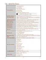
Recording Modes 

Continuous Recording   
Smart Recording 
Motion Recording 
Audio Recording 
Alarm Recording 
Manual Recording 

i


All modes can be triggered by schedule   


De-interlace Options 

Optimize for dynamic or static camera scenes 

Summary of Contents for NV 5000

Page 1: ...http www avermedia com http www averdigi com AVerMedia SA series SA5000 6000 6000E 7000H NV DOM series NV5000 6000 6000E 7000H SA6000E Pro User s Manual ...

Page 2: ...cular purpose Information presented in this documentation has been carefully checked for reliability however no responsibility is assumed for inaccuracies The information contained in this documentation is subject to change without notice In no event will AVerMedia be liable for direct indirect special incidental or consequential damages arising out of the use or inability to use this product or d...

Page 3: ...ITH YOUR LOCAL DEALER WARRANTY VOID FOR ANY UNAUTHORIZED PRODUCT MODIFICATION Manual Conventions The following conventions are used throughout this manual Caution symbol is intended to alert the user of the important installation and operating instructions Fail to comply may damage the system i Information symbol is intended to provide additional information for the purpose of clarification ...

Page 4: ...Connecting Device 17 SA6000E Pro Connecting Device 19 Familiarizing the Remote Control Buttons of SA6000E Pro 20 2 2 NV DOM Series Hardware Installation 23 2 2 1 Minimum System Requirements 23 2 2 2 DOM Installation 23 2 2 3 Installing NV5000 Card 23 2 2 4 Installing NV5000 and I O Audio cards 24 2 2 5 Installing NV6000 and I O card 24 2 2 6 Installing NV6000 Express 25 2 2 7 Installing NV6000E an...

Page 5: ...nd Save the Wanted Portion of the Recorded Video 40 3 8 To Bookmark a Section of the Video 41 3 9 To Search Using the Visual Search 41 3 10 To Search Using the Event Search 42 3 11 To Setup the PTZ IP PTZ Camera 43 3 11 1 Setup the PTZ Camera 43 3 11 2 Setup the IP PTZ Camera 44 Chapter 4 Customizing the DVR System 46 4 1 System Setting 46 4 1 1 To Set the POS Setting 49 4 2 Camera Setting 50 4 2 ...

Page 6: ... Familiarizing the Remote Console Buttons 81 7 3 1 To Setup Remote Console Setting 82 7 4 Using the Remote Playback 83 7 4 1 Familiarizing the Local Playback Buttons 84 7 4 2 Familiarizing the RealTime Playback Buttons 85 7 4 3 Familiarizing the Download and Playback Buttons 87 7 5 Using Handy Viewer to Access DVR server 88 7 6 Using PDA Viewer to Access DVR Server 88 7 6 1 To install PDA Viewer t...

Page 7: ...05 10 3 Remote Backup 109 Chapter 11 Using the Remote Control Server 111 Appendix A Registering Domain Names 112 Appendix B Removable Hard Disk Installation 113 Appendix C Configure UPnP 114 Enabling UPnP in Window XP 114 Appendix D Network Service Port 116 ...

Page 8: ......

Page 9: ...ithin the bundled software on personal computer AVerMedia NV DOM series are a 32 bit PCI video capture card with DOM that works as a digital video surveillance system It enables you to capture true color images and real time videos up to 16 camera inputs simultaneously 1 1 Package Contents SA5000 series Package 1 2 3 4 1 SA5000 series unit 2 Utility Software CD Manual included 3 Recovery DVD 4 Pow...

Page 10: ...r Cord NV5000 DOM Package 1 2 3 4 5 6 7 1 NV5000 Card 4 DOM cable 6 30cm Watchdog line 2 DOM 5 DOM power cable 7 20cm Video signal line 3 Utility CD Manual inculded NV6000 DOM Package 1 2 3 4 5 6 8 FC 26P 7 8 9 1 NV6000 card 4 DOM 7 I O cable 2 I O card 5 Utility CD Manual inculded 8 DOM power cable 3 2 x AV cable 6 30cm Watchdog line 9 DOM cable ...

Page 11: ... 6 30cm Watchdog line 9 DOM cable NV7000H DOM Package 1 2 3 4 5 6 8 FC 26P 7 8 9 10 1 NV6000 5 Installation CD 9 20cm Video signal line 2 I O card 6 30cm Watchdog line 10 DOM cable 3 2X AV cable 7 I O cable 4 DOM 8 DOM power cable If there is any damage shortage or inappropriate item in the package contact your local dealer immediately ...

Page 12: ...ps 480 400 fps Recording frame rate CIF 120 100 fps 240 200 fps 240 200 fps 480 400 fps 480 400 fps Recording frame rate VGA 60 50 fps 120 100 fps 120 100 fps 240 200 fps 480 400 fps Recording frame rate D1 24 20 fps 80 64 fps 80 64 fps 160 128 fps 160 128 Audio input 4 8 16 16 16 Sensor Relay Optional 4 4 4 4 4 4 4 4 DVD RW Yes Yes Removable HDD tray 2 HDD tray 2 HDD tray 3 HDD tray support up to...

Page 13: ...pport up to 4 HDD 1 HDD tray support up to 4 HDD 2 HDD tray support up to 4 HDD DOM 2 GB 2 GB 2 GB H W accesorry N A Remote controller N A Ethernet RJ 45 10 100 1000 Mbps RJ 45 10 100 1000 Mbps RJ 45 10 100 1000 Mbps USB 2 0 Front 2 ports Rear 4 ports Front 2 ports Rear 4 ports Front 2 ports Rear 4 ports LCD Display Temperarure Temperature System status HDD left size Alarm status N A Operation via...

Page 14: ...text on camera display image Advanced Event Log Viewer Details complete event logs according to your selection on event operation POS system and network events Alarm Triggered Mode Single event or multiple events as alarm trigger conditions Smart Alert Functions Launch EMAP Cam display Warning sound Email Make a phone call Send files to FTP SMS and MMS PTZ preset point tracking Alarm SOP wizard St...

Page 15: ...s relays and triggered status Attention Please Enable dialogs to trace if operator pays attention to security monitor Powerful Search By date time camera area event vision and log file Bookmark Easily save links to particular locations of recorded data and play them directly from the saved links POS Integration Compatible with most commonly used POS system Easy to add POS protocol Confidential Wor...

Page 16: ... Brightness Contrast Hue Saturation Sharpness Noise Reduction De interlace and Gray Scale of recorded data iStable Fix shaking and jolts impact on video with just one click 1 5 Hardware Introduction 1 5 1 Front Panel of SA Series 1 2 4 3 Name Function 1 Temperature display panel The panel will display the system current operating temperature 2 USB ports To connect external USB devices for backup 3...

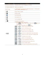
Page 17: ...key for multiple system control Press to enable multiple function modes and the button will turn to blue light To exit multiple function modes press again 1 Switch to single screen display mode 2 Switch to QUAD display mode 3 Switch to 9 spilt screen display mode 4 Switch to 16 spilt screen display mode 5 Switch to one single and 8 spilt screen display mode 6 Switch to one single and 13spilt scree...

Page 18: ... for entering password in playback and preview mode Channel camera selection number in playback and preview mode As a preset poison with in PTZ control mode 13 Number button 1 12 With button can switch to different screen display modes and enable auto scan function To call out 1 8 map figures in E map mode Playback control button in playback mode REV FWD Speed shuttle for adjusting reversed 1 2x 1...

Page 19: ...en the system is recording Network status indicator Lights when the system network connection is enabled 16 Touch Pad Work as a computer mouse Using to control cursor on the screen To open and close touch pad please follow the steps below 1 Push the touch pad to open the touch pad 2 The touch pad will open to 15 degree 3 To close the touch pad look for a button which under the touch pad bottom as ...

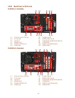
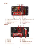
Page 20: ...ophone 7 Ethernet port 8 4 USB ports 9 Parallel and Com port 10 Keyboard and mouse plug 11 Power plug 12 Power switch SA5000 8 channels 2 4 7 8 9 10 6 1 3 5 12 11 1 Port to connect to I O box 2 4 Audio in ports 3 TV Out port 4 8 BNC video in ports 5 Com port 6 Audio Inputs speaker microphone 7 Ethernet port 8 4 USB ports 9 Parallel and Com port 10 Keyboard and mouse plug 11 Power plug 12 Power swi...

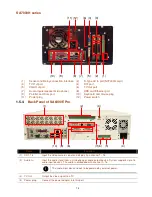
Page 21: ... microphone 8 USB and Ethernet port 9 Parallel and Com port 10 Keyboard and mouse plug 11 Power plug 12 Power switch SA6000E 1 2 5 8 9 10 11 12 7 6 4 3 1 DVI AV In port 2 Sensor and Relay connection interface 3 TV Out port 4 DVI port 5 VGA Out port 6 Power switch 7 Power plug 8 Audio Inputs speaker microphone 9 Ethernet port 10 4 USB ports 11 Parallel and Com port 12 Keyboard and mouse plug ...

Page 22: ...1 Power plug 12 Power switch 1 5 4 Back Panel of SA6000E Pro 1 2 3 10 9 8 7 6 5 4 Name Function 1 CH1 16 Input the video camera signal and display it on channel 1 16 2 Audio In Input the audio signal from a microphone or audio output device System supports up to 16 audio input devices The audio is embedded with channel 1 16 i The audio input device needs to be powered by external power 3 TV Out Ou...

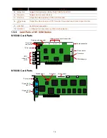
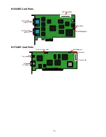
Page 23: ... one channel signal at a time 9 LAN Port For Ethernet connection 10 USB Port 4 USB port for connection any USB interface devices 1 5 5 Card Parts of NV DOM Series NV5000 Card Parts BNC video in ports TV out port Audio connector I O connector Reset pin Display card connector Video extension card connectors TV out link connector Watchdog pin NV6000 Card Parts D type AV IN port 01 TV out port I O con...

Page 24: ...16 NV6000E Card Parts DVI AV IN port 01 I O connector Reset pin Watchdog pin DVI AV IN port 02 NV7000H Card Parts D Type AV IN port TV out port TV out link connector Watchdog pin Reset pin I O connector ...

Page 25: ...n connect up to 16 video cameras 4 sensor devices 4 relay devices and output video to a TV or CRT LCD monitor Connecting the unit to a DVD RW external hard disk through USB connection the bundled software enables you to transfer and back up the recorded video Also the bundled software can playback and segment the backup recorded video SA5000 4 channels CRT LCD Monitor Camera 1 Camera 4 Microphone ...

Page 26: ...nels CRT LCD Monitor Camera 1 Camera 8 Microphone 1 Inte Inte Inte Inte r r r rnet net net net web viewer Notebook PDA viewer Handy viewer Microphone 2 SA6000 series Follow the illustration below to make the connection ...

Page 27: ...output video to a TV or CRT LCD monitor Connecting the unit to a DVD RW external hard disk through USB connection the bundled software enables you to transfer and back up the recorded video Also the bundled software can playback and segment the backup recorded video Follow the illustration below to make the connection ...

Page 28: ...ed of 2x 4x 8x 16x or 32x 5 To pause playing To move the selection to the left 6 To move the PTZ camera lens to the left To move the selection to the right 7 To move the PTZ camera lens to the right To zoom out view of PTZ camera 8 To zoom in view of PTZ camera To speed up movement of PTZ camera lens 9 To speed down movement of PTZ camera lens To focus in PTZ camera lens 10 To focus out PTZ camera...

Page 29: ...map figures in E map 16 A functional key for multiple system control Press to enable multiple function modes and the button will turn to blue light To exit multiple function modes press again Switch to single screen display mode Switch to QUAD display mode Switch to 9 spilt screen display mode Switch to 16 spilt screen display mode Switch to one single and 7 spilt screen display mode Switch to one...

Page 30: ...22 Name Function 17 Start recording video 18 To enable auto pan function ...

Page 31: ...r cable must be UNPLUGGED and all other cables that are attached at the back of the computer must be DISCONNECTED When installing multiple cards it is important to arrange the cards in sequence so that the cables would not tangle up 2 2 2 DOM Installation AVerMedia NV DOM series integrate the DVR software on a DOM Disk on Module User only needs to install the DOM and then the DVR software is ready...

Page 32: ... 2 IN 3 IN 4 TV OUT NV5000 card I O Audio card Channel 1 2 3 4 AUDIO IN 1 AUDIO IN 2 AUDIO IN 3 AUDIO IN 4 2 2 5 Installing NV6000 and I O card The NV6000 DOM can support up to 16 cameras and 8 audio inputs 1 Remove the PC case cover 2 Remove 2 brackets that cover the PCI slots Save the screws 3 Connect the NV6000 card and I O card with the connection cable 4 Press the cards into the PCI slot firm...

Page 33: ... 2 Remove 2 brackets that cover the PCI slots Save the screws 3 Connect the NV6000E card and I O card with the connection cable 4 Press the cards into the PCI Ex1 slot firmly 5 Secure the card with the screws 6 Connect the supplied AV connection cable to the DVI AV IN port NV6000 Express card I O card NV 6000 Express I O card AV connection cable AV connection cable 2 2 8 Installing NV7000H and I O...

Page 34: ...he labeled RESET SW switch lead and connect it to the NV6000 card reset pin 2 Connect the supplied Watchdog line to the NV6000 card watchdog pin and the other end to the motherboard RESET SW panel If you are not sure please refer to the motherboard user manual 3 You may now replace back the PC cover and connect all the cables NV6000 Reset SW lead Watchdog line 2 2 11 Connecting the Watchdog line t...

Page 35: ...than one card please refer the sequence of the camera to the number of cards installed in installing the card section 2 Connect one end of the RCA video cable not supplied to the TV OUT port of NV3000 5000 card and the other end to the TV video input port If you are not sure please refer to the TV user manual NV 5000 Camera 1 Camera 2 Camera 3 Camera 4 RCA cable Television IN 1 IN 2 IN 3 IN 4 TV O...

Page 36: ...6000E 1 Use the supplied AV connection cable and connect it to the D type AV IN port of NV6000E card see NV6000E card parts 2 Connect the cameras to the BNC video connectors and audio devices to the RCA audio connectors Just follow the order basing on the marked sequence 3 Connect one end of the RCA video cable not supplied to the TV OUT port of NV6000E card and the other end to the TV video input...

Page 37: ...ipment Connecting the POS equipment to AVerMedia NV DOM series DVR system thru RS232 connection enables you to view record and keep track of the items that were sold You may also select the camera on where to display all the data To connect locate the RS232 port of the POS equipment and PC Use an RS232 cable not supplied to make the connection For more detail please refer to POS user manual RS232 ...

Page 38: ... which pinhole is assigned to sensor input and relay output SENSOR IN RELAY OUT G 1 2 3 4 1 2 3 4 G G G 1 2 3 4 N A N A N A N A 1 2 3 4 5 6 7 8 9 10 11 1213 1415 16 17 1819 20 The signal from the sensor i e infrared sensors smoke detectors proximity sensors door sensors etc is being transmitted to the I O card and this triggers the system to respond and send signal to relay device i e alarm teleph...

Page 39: ...R USB Receiver Part Connection 2 4 1 SA Series USB Port IR sensor 2 4 2 NV DOM Series OSD Kit is an optional item for NV DOM series User can purchase with your local dealer if it is necessary USB Port IR sensor ...

Page 40: ...t dialog box In the logout dialog box you may do the following Click Exit to close the DVR program Click Login to sign in in different account Click Compact to switch to compact mode Click Cancel to exit Logout dialog box Click About to update patch or find about the software info 2 Volume Adjust the audio volume to a proper volume 3 Split Screen Mode It provides 7 kinds of split display modes for...

Page 41: ...again to disable all inbound connections 7 Setup When setting up the system for the first time type the word admin in the Password text box to access Click button to configure settings for cameras recording network scheduler backup sensors relays alarms and user authentication 8 PTZ Click to pop up a PTZ setup dialog to configure an appointed PTZ camera 9 Preview Switch to Preview Advanced mode Th...

Page 42: ... the arrow icon When you switch to full screen in multiple screen mode Left click to toggle to only display one of the video in the multiple screen mode or all 17 Alarm Click to view the status or advanced alarm information 18 On Screen Keyboard If the keyboard is not available you may use the Virtual Keyboard Click the arrow icon to leave from full screen display mode ...

Page 43: ...vent log click POS Viewer bar to call out the POS event log window 1 2 3 4 5 6 Name Function 1 POSDB Path The storage path for POS event log Click to change the storage path 2 Before After Set a time period before and after of POS event log 3 Channel Select the POS event log of channel 4 Search String Enter specific key word or word string to search the POS event log Mark the Match whole word exac...

Page 44: ...yed You may move the bar to seek at any location of the track 3 Hour Buttons Select and click to playback the recorded video file on the specific time frame i The Hour buttons represent the time in 24 hour clock The blue bar on top of the hour button indicates that there is a recorded video file on that period of time While the red bar indicates that you are currently viewing the recorded video fi...

Page 45: ...ay the video To return press the right button of the mouse or ESC on the keyboard or click the arrow icon When you switch to full screen in multiple screen mode Left click to toggle to only display one of the video in the multiple screen mode or all i When there are dual monitors with 32 channels the full screen mode will split into 16 channels on each monitor 15 Event log Show the record of activ...

Page 46: ...t screen mode When you are in single screen mode Right click and Drag a square on the area you want to enlarge When you are in multiple screen mode Right click the video screen of the camera and Drag on where you want to locate it To only display one of the video in the multiple screen mode Left click the video screen you want to display 2 AutoScan Start Stop video screen cycle switch 3 Alarm Aler...

Page 47: ...ct the camera and click the preset position number and save it 9 Camera lens speed controller Adjust the moving speed of the PTZ camera lens 10 Camera preset position number Move the PTZ camera to the preset point 11 Group AutoPan Select to automatically operate PTZ camera in group 3 6 Setting Up and Using the EMAP EMAP can hold up to 8 maps in bmp jpg format You may locate the camera sensor and r...

Page 48: ...he map and to display the video at the upper right corner of the EMAP screen At the lower right corner of the EMAP screen it lists all the warning message 3 Click Exit to close EMAP screen 3 7 To Cut and Save the Wanted Portion of the Recorded Video 1 Use the Playback Control buttons or drag the bar on the playback progress bar and pause on where you want to start the cut Then click Segment to set...

Page 49: ...bookmark is protected the file won t be overwritten The protected bookmark file will be deleted when the Delete the recorded data is enable in the System setting also refer to 4 1 System setting 3 Select and click one in the bookmark list to preview the file 3 9 To Search Using the Visual Search 1 Click Visual Search 2 In the Visual Search Setting dialog box select the Camera number and the date T...

Page 50: ...art searching 5 When the Event list appear click and select the item you want to view To Search Using the Intelligent Search 1 Click on the video screen on where you want to search 2 Click Intelligent Search The Intelligent Search text red would appear at the lower left corner of the screen 3 When the Intelligent Search Setting dialog box and motion detector frame appear you may adjust the sensiti...

Page 51: ...click Save to keep the settings 6 Repeat step 4 5 if you want to save another PTZ camera position 7 Restore AutoPan Time set a time period for restoring auto path function after the PTZ camera has been moved Mark the check box and set the time period in second 8 Click Advanced Settings to enable the on screen PTZ control function Mark Enable check box to enable the control arrow and tools on the P...

Page 52: ...for how long the IP PTZ camera stays in that position before it moves to the next one If you want to add description check the Show Preset Name box and in the Preset Name text box type the word When done click Save to keep the settings 7 Repeat step 4 5 if you want to save another PTZ camera position 8 Restore AutoPan Time set a time period for restoring auto path function after the IP PTZ camera ...

Page 53: ...cons will display on the screen User can click arrow to adjust the direction of PTZ camera click tool icons to focus in out and zoom in out If the camera is not a PTZ camera the PTZ control arrow won t work 10 When done click OK to save the setting or Click Cancel to leave without saving the new setting ...

Page 54: ...w to assign or connect to a network drive please refer to your Windows help file and search Map Network drive By default the data is stored in C Data to insert another storage path click Add To remove the selected path click Delete If you want the system to automatically erase the data after a certain days enable the Delete recorded data after check box and enter the numbers of days in Days text b...

Page 55: ...onitoring the system must enter the same number that appears from the left box at the right text box and then click OK 6 TV Out Select the camera you want to appear on TV and set the time gap from 3 to 10 sec before it switches to the next camera Advance button The Advance functions only for NV6000 Express Select the channel and camera user want to display on TV In Advance mode user has two types ...

Page 56: ...ange the e mail settings click Setup Beep if no signal Make sound when the video signal is lost Playback Mode Select the mode of playback the video Select date and time Select the date and time which user wants to playback Play the last file Automatically playback the video from the last hour Instant Playback Automatically playback the video which has just recorded Date Format Select the date form...

Page 57: ... Windows 2000 or Windows XP system requirements 4 1 1 To Set the POS Setting In the System Setting dialog box POS section click Setting To set the text flow and color format click Advance 1 In the POS Console Setting dialog box click Add to set a new POS setting Modify to change the POS setting and Delete to remove the selected POS setting Click OK to save and close POS Console Setting 2 In the PO...

Page 58: ... saving and click Default1 Default2 to revert back to original factory setting 1 Camera Icons Select the camera number you want to adjust the video setting To select all the cameras enable the ALL check box To select more than one camera Right click on the camera icon To select one camera only Left click on the camera icon The camera icon turns red when it is selected 2 Enable Set to enable disabl...

Page 59: ... Display the video of the selected camera 10 Input Select the type of video camera input you are using Analog Camera The video source is coming directly from camera that is connected to the SA Series PCI card Remote DVR The video source is coming from another DVR server In the Remote DVR dialog box enter the server IP port number user ID password and select the camera number If you are not sure of...

Page 60: ...ount the objects that move between the selected regions 4 Click Object size to define the detected object dimensions Press left button of mouse and drag on the screen To see the object size frame on screen enable Moving Object in Display section 5 Adjust the sensitive of object detecting 6 To test the setting mark the Directions In Out want to be test and click Start The testing result will show i...

Page 61: ... screen The recording modes are listed below Always Recording Record the video from the selected camera and save it to the designated storage path see also Chapter 4 1 1 Motion Recording Start recording the video from the selected camera only when the system detects movement Once a motion is detected the system automatically saves the previous frames and stop based on the Start Record Prior and St...

Page 62: ...the Enable Deinterlace mode to 1 if you are capturing motionless picture and 2 if it captures lots of movement 9 Video Screen Display the video of the selected camera 10 Mask Shield Edit Mask mark an area on the screen to disregards the motion in the marked area and to only monitor outside the marked area As for the Shield it covers an area on the screen and the covered area would not be visible o...

Page 63: ...OM 7000H doesn t support shield function 4 3 2 To show and change the color of the Mask 1 Enable the Show Mask check box 2 In the Color section select the color and click button 4 3 3 To Playback Encrypted Video On Playback Webcam and Remote Console video screen just click and enter the correct password to decrypt and playback the video To encrypt the recoded video back click and enter a WRONG pas...

Page 64: ...r the remote accessing port in Port column The default value is 5555 i User also can manually run this function To run click Start Programs DSS Tool Remote Control Server The remote control server icon appears on the taskbar when the remote control server is enabled also see Chapter 11 6 Network Video Configuration Set up the video quality and frame rate for viewing and transmitting to the remote ...

Page 65: ...ic synchronize time on a daily basis Or user can click Synchronize Time Right Now to adjust time right away 10 Other Configuration UPnP Enable UPnP function to automatically configure the port setting on the local network This function is available when there is UPNP device in the same network It will write the DVR port information into the router or other network device see Appendix B Enable Whit...

Page 66: ...VR remote system to access at the set time After the appointed time the Network function will be disabled If the Network function is already enabled the Network function will not be disabled when the appointed time has ended Reboot Restart the PC at the appointed time i Make sure the Windows operating system is set NOT to require you to login user name and password This way the system will be able...

Page 67: ...s selected The block that appears in white doesn t have data If you want to set the specific time right click on the selected block Then set the time to start and end 3 Check the information beside the calendar Selected Files Show the number of files selected Require Space Show the total size of the selected file 4 Enable Auto partition and select to divide the file size into DVD R or CD R DVR aut...

Page 68: ...ct the sensor ID number 2 Enter sensor name 3 The system automatically detects the card and input number In the Content section enter sensor description 4 In the test section click Test to check the sensor status Red is high and Green is low 5 Click OK to exit and accept the setting and Cancel to exit without saving the setting 4 8 Relay Setting The I O device must be installed to use this functio...

Page 69: ...Default to revert back to original factory setting 1 2 3 4 5 6 7 To set the Alarm Setting 1 Click Add to insert and set a new alarm setting Click the items in the 7 Alarm Setting List if you want to modify the alarm setting 2 In 1 Alarm Setting number Name Description display the selected alarm setting number in the list below Enter alarm name and description 3 In 2 Enable Time the number from 00 ...

Page 70: ...twork connection of DVR system is lost the system will send out the alarm message Hard Disk failed when the hard disk can t work normally the system will send out the alarm message Temperature set a temperature limited of system for system to alarm When DVR system temperature is over the temperature limited the system will send out the alarm i Temperature setting only supports on NV6000 Express ca...

Page 71: ...as an alarm occurred and then the channel video that has an alarm occurred will be enlarged on screen Camera 1 32 the selected channel video that will be enlarged on screen when an alarm is activated b Retrieve time set the waiting duration before system switching back to original Preview mode If the retrieve time is un mark the alarm video will keep enlarging until user switch back to Preview mod...

Page 72: ... party Click Detail and click to locate the program path Enable Multiple instance check box to allow the program can be executed many times at the same time Snapshot Take a snapshot when the alarm is activated a Select Camera specify which channel video to be snapshot when the alarm is occurred Alarm Camera when a channel has an alarm occurred and then the DVR system will snapshot the channel vide...

Page 73: ...ure you have microphone connected to your PC 5 Click OK to exit and accept the setting and Cancel to exit without saving the setting 4 9 3 To Setup Call Out List 1 Beside the Make Phone Calls check box click Detail 2 In the Call Out List click Add to insert a new contact number Modify to edit the selected item Remove to delete the selected item Test to check if it is working 3 In the Call Out Sett...

Page 74: ...rames Attach image when sensor is triggered When the sensor is triggered the system will capture the image and send the image to the certain e mail address with the alarm message 4 Modem Dial up Setting If you are using dial up modem enable Auto Dial up check box and select the modem name You may also set the time to disconnect automatically just enable the Auto Disconnect after check box and set ...

Page 75: ...ou may now set to send thru SMS or MMS If you enable SMS setting just enter the message in the text box If you enable MMS enter the APN name WAP IP MMS address and the message If you are not sure please contact your mobile service provider 5 Attach image when sensor is triggered select the camera that the images will be capture and send when the sensor is triggered 6 Click OK to accept the new set...

Page 76: ... 4 9 11 To Setup POS Keyword Setting 1 Beside the Send to POS Keyword check box click Detail 2 In the POS Keyword Setting select the camera to enable disable scanning the keyword Enable All to select all cameras 3 Enter the text below keyword text box Click Add to include the keyword in the list To remove select the word in the list and click Delete You may only add 8 keywords User can define the ...

Page 77: ... OK to save and exit the setup windows To exam the setup condition click Start Test 1 Select the camera number 0 16 and press right button on the mouse to call up the setup windows And then click the Suspicious Object Tab 2 Click Save to capture the image for comparing reference To view the captured image enable the Show Reference Image check box The captured image will display on screen The refer...

Page 78: ... the camera movement range which compare with the original position 7 Enable Mask Mark an area on the screen to disregards the motion in the marked area and to only monitor outside the marked area Mark the Enable Mask check box click and drag the mask frame on the screen 8 To reset all object frames click Clean To clean an object frame click right button of mouse and drag the object frame that use...

Page 79: ... Allow the user to view the event log from remote site Remote EMAP Allow the user to view the E map of DVR from remote site IP Camera Enable disable user to add new IP camera when using the Web Viewer Remote Access Time Enable Infinite check box to access DVR without time limit If you want to set time limit enter the number of minutes in Minute text box 4 Visible Camera Select the camera number th...

Page 80: ...plit screen types to view all the video at the same time The only difference is that there are no Preview and Playback buttons To run the application go to backup folder and double click QLogViewer or Player icon 5 1 Familiarizing QLogViewer Buttons 9 1 3 2 4 5 6 7 8 Name Function 1 Time Display the file date time and play speed 2 File Display the path where the file is located 3 Playback Control ...

Page 81: ...he Player Buttons 3 5 4 6 8 7 10 9 11 12 13 14 17 16 15 1 2 Name Function 1 Split Screen Mode Select from six 6 different split screen type to playback the recorded video file of all the camera or one camera over the other or alongside on a single screen i If there are only 4 cameras you won t be able to switch to 9 16 and 13 split screen mode To zoom in an area on the screen Right click and Drag ...

Page 82: ...mode click the camera ID number to switch and view other camera 9 Output Save the segmented file in mpg avi or dvr format see also Chapter 3 7 10 Segment Keep a portion of the recorded video you want see also Chapter 3 7 11 Print Print the screen shot 12 Snapshot Capture and save the screen shot either in jpg or bmp format 13 Full screen View in Playback compact mode To return Right click the mous...

Page 83: ...s Function Keys Description F1 Display system information F2 Start recording F3 Enable network function F4 Access system settings F5 Switch to playback mode F6 Access EMAP setting F7 Access PTZ camera control panel F8 Snapshot F9 Switch to Full Screen F11 Switch to AutoScan Ctrl A Turn on off hardware AGC Auto Gain Control ...

Page 84: ...ure for the first time you will be prompted by your browser to install WebCamX cab allow the installation and you should be able to connect and login afterwards For Windows 2000 click Yes when the Security Warning dialog box appears For Windows XP click Install when the Internet Explorer Security Warning dialog box appears After installing the WebCamX cab and when connecting to the DVR server you ...

Page 85: ...on If the DVR server Talk to web client setting is disabled you won t be able to hear from the other side 7 Record Save the video of the selected camera in AVI format 8 Event Log Viewer Display the Event logs Operation logs POS logs System logs and Network logs 9 Remote Console Initiate Remote Console The interface is the same as DVR application and allows you to control DVR server see also Chapte...

Page 86: ... 1 1 To Setup Remote System Setting Click OK to exit and save the setting and Cancel to exit without saving the setting The setting here applies to Remote DVR only 11 12 13 14 10 1 9 8 7 6 5 4 3 2 1 Camera Name Select the camera you want to adjust the settings 2 Enable Set to enable disable the selected camera When there is no video source on the camera we suggest disabling it so that the system w...

Page 87: ... records at the minimum frame rate setting Set the maximum and minimum frame rate setting in 7 Frame Rate section No Recording The system won t do any recording 8 Motion Detection Adjust the sensitivity of the motion detector The higher the value the finer the sensitivity is detected When it detects a motion a green triangle mark would appear at the upper left corner of the screen 9 Voice Detectio...

Page 88: ...t PTZ dialog box Select column click to enable disable viewing and controlling the PTZ camera Click OK to exit and save the setting and Cancel to exit without saving the setting 3 AutoPan Groups Operate the PTZ cameras automatically based on the selected camera group preset position number 4 Camera preset position number Move the PTZ camera to the preset point 5 Zoom Zoom in and out the image 6 Fo...

Page 89: ... the Remote Console setting see also Chapter 7 3 1 8 Preview Switch to Preview Advanced mode This allows you to view live camera display 9 Playback Switch to Playback mode This allows you to view the recorded video file see Chapter 7 4 10 Status Bar Display the current date time and hard disk free space 11 Camera ID Show the number of cameras that are being viewed When you are in single screen mod...

Page 90: ...lected path click Delete If you want the system to automatically erase the data after a certain days enable the Delete recorded data after check box and enter the numbers of days in Days text box 2 Language Customize the system to display the tool tips and dialogs based on the selected language By default the language is in English 3 Remote Server Enter the DVR Server IP and Port number 4 Channel ...

Page 91: ...00 to 23 represent the time in 24 hour clock The numbers from 01 to 16 represent the camera number To Make a Selection 1 Select the date in the calendar Use and buttons to shift the calendar to the left or right 2 In the table below click on the blue block to select and open the recorded file The blue block turns red when it is selected The block that appears in white doesn t have data You can onl...

Page 92: ... a recorded video file on that period of time While the red bar indicates that you are currently viewing the recorded video file 4 Playback Control Buttons Begin Move at the beginning of the recorded video file Previous Go back to the previous frame Slower Play the recorded video file at the speed of x x or x Rewind Wind back the recorded video file Pause Briefly stop playing the recorded video fi...

Page 93: ...e Left click to toggle to only display one of the video in the multiple screen mode or all 7 4 2 Familiarizing the RealTime Playback Buttons 2 4 3 5 6 9 8 7 10 11 1 Name Function 1 Split Screen Mode Select from two 2 different split screen type to playback the recorded video file of all the camera or one camera i If there are only 4 cameras you won t be able to switch to 9 16 and 13 split screen m...

Page 94: ...represent the camera ID The blue colored column indicates that there is a recorded video file on that period of time While the red colored column indicates on where to start playing the recorded video file 6 Preview Switch to Preview Advanced mode 7 Playback Switch to Playback mode This allows you to view the recorded video file 8 Status bar Display the recorded date time and play speed 9 Camera I...

Page 95: ... speed of x x or x Rewind Wind back the recorded video file Pause Briefly stop playing the recorded video file Play Play the recorded video file Faster Play the recorded video file at the speed of 2x 4x or 8x Next Go to the next frame End Go to the end of the recorded video file 3 Date Open other file 4 Output Save the segmented file in mpg or avi format 5 Print Print the screen shot 6 Save Save t...

Page 96: ...r and is connected to the internet To use this feature you need to install the PDA Viewer software either thru ActiveSync connection or download it from the internet Please check if your PDA meets the 2 requirements below OS MS Windows CE 4 0 PocketPC 2002 2003 Mobile 5 PDA version CPU ARM architecture 7 6 1 To install PDA Viewer thru ActiveSync 1 Connect your PDA to your PC Place the CD into the ...

Page 97: ...ed to the internet 2 Open the web browser and enter the server IP Then click the hyperlink Download PDA Viewer 3 When the Download dialog box appears enable Open file after download and click Yes 4 After the installation the PDA Viewer 5 5 icon will appear in the Programs list ...

Page 98: ...to switch and view different camera number or channels 3 About Display the PDA Viewer software version 4 Minimize Reduce the size to taskbar 5 Exit Close the PDA Viewer 6 Focus Adjust the focus of PTZ camera to produce clear image 7 Full Screen Use the entire screen to only display the video 8 Snapshot Capture and save the screen shot in bmp format 9 Zoom Zoom in and out the PTZ camera image 10 Di...

Page 99: ...am that it can be downloading it from the DVR server through the internet To install JAVA Viewer from the DVR Server 1 Open the web browser and enter the DVR server IP http DVR server IP port JAVA Viewer html Then click Connect 2 When the Download screen appears select JAVA Viewer jad and download it to your mobile phone 3 After the installation the JAVA Viewer will be in your mobile phone system ...

Page 100: ...elect the Connect to connect to DVR server 4 Click Yes to accept the data from DVR server 5 When connection is success you will see the camera video on the screen 6 To switch to different camera view select menu and select the channel 7 The JAVA Viewer support PTZ control function you can refer to Help file for detail function control key Select menu and go the way down to select the Help file ...

Page 101: ...m 1 Click Start Programs DSS ImageVerification 2 In the ImageVerification screen click Load Source Image and locate the image source 3 Click Verify Image to begin the process 4 Check the result in the Processed Image screen If the picture is unmodified the image in the Source Image and Processed Image screen would be exactly the same If the picture is being modified a warning dialog box would prom...

Page 102: ...avi format 5 Print Print the screen shot 6 Segment Mark the beginning and the end of the wanted portion of the video Two triangle marks will appear on the slider To cancel video segmentation click this button again 7 Zoom Buttons Enlarge reduce and set the image back to normal size 8 Full Screen Use the entire screen to only display the video 9 Default Set the video back to original state and dele...

Page 103: ...the name of the selected setting in the temporary setting block 23 Delete Permanently remove the selected setting in the temporary setting block 24 Load Setting Call the saved settings 25 Save Setting Store the settings in the temporary setting block 9 1 To Use iStable The iStable function can reduce the jolt in the recorded video 1 Click Open File button and select the recorded video 2 And then c...

Page 104: ... Dispatch program 1 Make sure you are connected to the internet 2 Click Start Programs DSS Tool Dispatch 3 In the DVR Server section enter the DVR server IP port user ID and password You can also select to display the language you prefer 4 Auto connect when star Enable to automatically connect the dispatch server when start up 5 In the Dispatch Service section if you have installed more than one n...

Page 105: ...er The default is 80 User ID fill in the remote DVR server s login account Password fill in the remote DVR server s login password Description fill in a short description for the remote DVR server 3 Click OK to complete adding remote DVR server 4 The added DVR server will be listed and auto connects to DVR server 5 Once the connecting is success user can start to configure DVR server 6 When connec...

Page 106: ...r camera video system If the video system setting is wrong the video would appear abnormal 4 Attention Please Check the attentiveness of the person who is monitoring the system You may set the number of times the Attention dialog box to appear in a day in Times per day text box When this feature is enabled the Attention dialog box would appear The person who is monitoring the system must enter the...

Page 107: ...ct to network when the DVR is executed Login to compact mode Switch to compact mode directly when the DVR is executed 8 POS Set from which camera screen to display the data from the POS equipment To set the text flow and color format click Advanced 9 UPS Uninterruptible Power Supply Protect the system from damaging such as power surges or brownouts This automatically gives time to close the DVR pr...

Page 108: ...st disabling it so that the system won t detect it as video loss error 3 Camera Display Enable disable to show the video Even if the video of the selected camera is hidden you can still record the video and preview it in playback mode Name Change the camera name Description Add a short comment 4 Video Adjustment Adjust the Brightness Contrast Hue and Saturation of the selected camera 5 Noise Reduc...

Page 109: ...low Always Recording Record the video from the selected camera and save it to the designated storage path Motion Recording Start recording the video from the selected camera only when the system detects movement Once a motion is detected the system automatically saves the previous frames and stop based on the Start Record Prior and Stop Record After settings Smart Recording Automatically switch to...

Page 110: ...rd for color picture compression rate MPEG4 uses higher compression rate and smaller file size While MJPEG uses slightly lower compression rate and bigger file size MPEG4 MPEG 4 Encryption H264 MJPG NV DOM 3000 NV DOM 5000 NV DOM 6000 NV DOM 6000 Express NV DOM 7000H Network Setting In the Network Setting dialog box click Update to accept the new settings click Exit to exit without saving and clic...

Page 111: ...the Talk to Web Client is disabled the person in the DVR server side can only hear the voice from the client side that is when the WebCam 2 Way Talk button is activated See also Chapter 7 1 6 The default port of voice phone is 9999 8 Network Time Synchronization Adjust the DVR system time same as network time server Fill in the Time Server IP address or domain name Select Automatic Synchronize tim...

Page 112: ... Recording setting see also Chapter 4 3 Backup Save another copy of all the data at the set time and specified backup path DVR automatically updates and only backup the data that are not yet included in the archive Network Activate DVR remote system to access at the set time After the appointed time the Network function will be disabled If the Network function is already enabled the Network functi...

Page 113: ...ant to activate or deactivate the alarm function When it is deactivated the color of the block turns white 4 In 3 Conditions you can set Trigger if any to activate if it falls to one of the conditions or Trigger if all to activate if it falls to all conditions In Camera section select and click on the camera number 01 to 16 in Motion Detected and Video Loss to set the condition for the system to a...

Page 114: ...the alarm to set the reset condition of alarm Once alarm is reset all alarm action will stop at the moment If the sensor normal status is high set the sensor condition to low 7 In 6 Action you may now set the alarm action for the system to perform when the alarm condition is activated Launch E Map Display mini Emap screen TV Out Switch to only display the video on TV from where the alarm is activa...

Page 115: ...alog box click OK to exit and save the setting and Cancel to exit without saving the setting 1 Mail Server Enter the SMTP Server and port If your e mail system requires user identification enable Authentication check box and enter User ID and Password 2 Mail To check if it is working click Test Account button From Enter the sender e mail address To and CC Enter the recipient email address and sepa...

Page 116: ...ction select As Setting to record the number of frames based on the Recording Setting or Max to record the maximum of frames based on the available speed 4 In the Stop Recording after text box set the number in second for the program to continue recording after the alarm has ended 5 Click OK to accept the new settings and Cancel to exit without saving To Setup Alarm SOP Beside the Alarm SOP check ...

Page 117: ...the recorded data at a time starting from the specified date As for Manual Backup it only archives the recorded data of selected date i To back up the data you must have at least 2G hard disk space To back up the recoded data from the DVR server 1 Make sure you are connected to the internet 2 Click Start Program DSS Tool Remote Backup 3 To add the DVR server click Add 4 In the Add New DVR windows ...

Page 118: ...s will start when user press the backup button Click File Select to choose the date time and camera you want to back up Click Browse to set the storage path 6 Click OK to complete the adding DVR server The added DVR server will display in Remote Backup main windows 7 Click Start to begin backup and click Stop to stop backup progress 8 For manually backup click file select button and select the DVR...

Page 119: ...ny need to manually run this program for CMS access the DVR server To run click start Programs DSS DVR Remote Control Server The remote control server icon appears on the taskbar when the remote control server is enabled To change the port setting or stop server right click icon and then make a selection i User can also setup Remote Control Server in DVR Network setting please see Chapter 4 4 5 ...

Page 120: ...tem as CD Key number and select the product name The CD Key of MAC address input format shall be 12 digits without colon or hyphen To find MAC address of your DVR system follow the steps below In OSD menu select NETWORK SETUP Select any one of IP mode A NETWORK INFORMATION windows will show up MAC address of DVR system is display as shown Then click OK to login or Reset to clear the previous input...

Page 121: ...t the jumper to the right position 1 Unlock the removable hard disk drawer then pull it out 2 Connect the power connector to the hard disk master 3 Carefully insert the hard disk in the removable rack 4 Slide the drawer back 5 Lock the removable keylock Before removing the removable hard disk drawer the DVR Unit must be TURNED OFF and unlock the removable hard disk drawer keylock ...

Page 122: ... be configured to use UPnP UPnP must be enabled on your router Please contact your local router dealer or refer to the router user manual for the UPnP configuration on router Enabling UPnP in Window XP 1 Go to Start Setting Network Connections And then the below windows appear 2 Right click on Local Network Connection icon and select Properties Advance tab The below windows appear 3 Click Settings...

Page 123: ...115 4 Mark the UPnP Framework check box and click OK ...

Page 124: ...following table shows the ports that DVR server uses for certain network service Port Variable Remote Console CM 3000 5550 Y WebCam 80 Y 2 way audio 9999 Y Remote Control CM3000 RC1000 5555 Y DVR POS 5150 Y DVR DDNS Upload Download 53 1053 N ...

Page 125: ...sed with the product 4 AVerMedia TECHNOLOGIES Inc does not warrant that this product will meet your requirements it is your responsibility to determine the suitability of this product for your purpose WHAT WE WILL AND WILL NOT PAY FOR We will pay labor and material expenses for covered items However we will not pay for the following 1 Removal or installation charges 2 Shipping charges 3 Any incide...

Reviews: