AVG-UDATP4
Cascade connection diagram:
Cascade through IR Loop
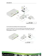
Connect the IR LOOP socket of the first AVG-UDATP4 and the IR IN socket of the
next until all th eAVG-UDATP4 units have been connected.
Sending IR signals to the IR Receiver connected to the first AVG-UDATP4 will
control all cascaded AVG-UDATP4’s.
Cascade through RS232 Loop
Connect the RS232 LOOP socket of the first AVG-UDATP4 and the RS232 IN
socket of the next until all the AVG-UDATP4 units have been connected.
Sending RS232 commands will control all cascaded AVG-UDATP4 simaltaneously.
Note: To identify the AVG-UDATP4 in cascading, please set a unique ID for each
unit when the cascade connection is done.
4.6. Twisted Pair Cable Connection
The twisted pair used in the AVG-HD402PR MUST be a straight-through cable. The
connectors can be T568A or T568B, but both sides must be the same
Summary of Contents for AVG-UDATP4
Page 20: ...AVG UDATP4 7 Panel Drawing ...


