9
Warnings and precautions
INTAKE AND
EXHAUST VENTILATORS
The manufacturer recommends consulting the regulator installation guide for connection to the
variable board and the ON / OFF relays.
The manufacturer recommends a maximum of six Avi35 pickups by Gev2 accessory card
amplifier for Genius Itouch.
The manufacturer recommends a maximum of three Avi 35 per variable relay card from a
Genius Itouch controller.
The manufacturer recommends a maximum of five Avi35 per variable relay card from a
MAXIMUS controller.
EXHAUST VENTILATORS
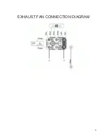
must be connected in parallel to a variable relay of the regulator.
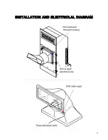
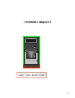
Drill the plastic on the side of the shutter to pass the wire. Drill diagonally to reach the plastic
piece that supports the
EXHAUST VENTILATOR
. Keep enough space to allow the louves to
open without touching the electrical wire. See diagram.
The
INTAKE
VENTILATORS
must be connected in parallel to another variable relay of the
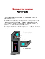
regulator. Drill the upper right corner of the inlet fan housing to pass the wire and probe wire.
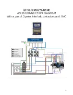
The manufacturer recommends using the same common L2 for the 230V solenoid valve of the
wash system, as well as the relay contactors and the AVi35
INTAKE
and
EXHAUST
VENTILATORS
.
The manufacturer recommends installing a bipolar mechanical switch to each fan.
The manufacturer recommends a 3-wire cable to connect the
EXHAUST VENTILATOR
motor
to the bipolar mechanical switch associated with the
EXHAUST VENTILATOR
.
The manufacturer recommends a 6-wire cable to connect the
INTAKE
VENTILATOR
motor to
the
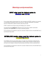
DPDT
relay or the
INTERLOCK
relays and the bipolar mechanical switch associated with
the
INTAKE
VENTILATOR
.
The manufacturer recommends a 3-wire cable to connect the solenoid valve.
The gauge of the wires must respect the electrical code in force in your area.
Summary of Contents for AVI35
Page 1: ...Installation and User Manual...
Page 2: ...2...
Page 10: ...10 INSTALLATION AND ELECTRICLAL DIAGRAM...
Page 11: ...11 INSTALLATION AND ELECTRICLAL DIAGRAM...
Page 12: ...12 Maximus AVI 28 CONNECTION DIAGRAM...
Page 14: ...14 EXHAUST FAN CONNECTION DIAGRAM...
Page 15: ...15 INTAKE FAN CONNECTION DIAGRAM...
Page 16: ...16 Installation Guide...
Page 18: ...18 Installation diagram 1...
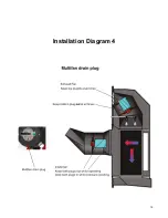
Page 19: ...19 Installation Diagram 4...


