OPERATION AND INSTALLATION MANUAL
EN-1320
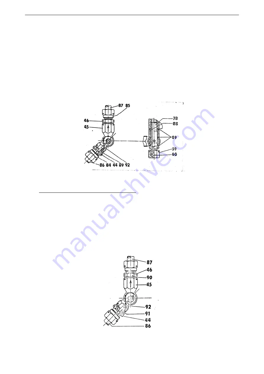
Install new sealing rings 89 onto the turning screw 78 and the feedback body 45 with ring 88 in position
shown, it is arrow up – figure 12-36 – and screw the turning screw into the governor body without final
tightening. The ball 92 shall be in socket 44.
WARNING: USE ONLY ALLOWED SEALING RINGS (ALUMINUM).
Reinstall back both removed tubes 86, 87. Tighten finally the turning screw 78 and the tubes 86 and 87
carefully with continuous tightening of all tube cap nuts and turning screws. Tighten the tubes also on the
second end.
Finally secure the turning screw 78 with the nut 59 and both tube cap nuts with lock wire, using standard
locking procedure. Secure also the second end of the tubes.
Figure 12-36 Sealing ring replacement
(6) Replacement of non-return valve body sealing rings
In case of leakage from the non-return valve body, replace sealing with following procedure:
Remove lock wire from tube cap nuts 86 - figure 12-37 - or the tube cap nut 87 or both. Remove the tube
86 and 87 (or both).
NOTE: Before you will remove the tubes, it is necessary to loose also the second end of the tube.
Replace the sealing ring 90 or 91 with new one after fitting 46 removal or the fitting 44 from the non-return
valve body.
Figure 12-37 Replacement of non-return valve sealing
61-10-20
PROPELLER CONTROL SYSTEM
(Installation With Jihostroj LUN-Series Governor)
Page 12-40
2017-10-06


