background image

8

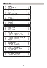
PARTS LIST

No.

Description

Qty.

1

Motor__RS380_ 3.6V

1

2

Motor gear

1

3

P_ 039__08A_ Gearbox cover

1

4

ISO 7045- M2.5x 5-Z --- 5S

2

5

Washer

1

6

Back star gear__plastic

3

7

Back star gear holder

1

8

Front star gear_ steel

3

9

Ring gear

1

10

Self lock block

1

11

Locking pin

6

12

Self lock ring

1

13

Lock washer

1

14

Self lock core

1

15

Bushing

1

16

Gearbox front

1

17

Pressure pin 3mm

3

18

Output axis

1

19

Pressure washer

1

20

Torque spring

1

21

Screw ring

1

22

P_ 039_ 10A_ Adjusting ring_ rear

1

23

P_ 039__11A_ _Adjusting ring_ front

1

24

P__039_ A03A_ PCB batterybar

1

25

P_ 039_ 03A_ Housing main_ upside__left

1

26

P_ 039_ 12A_ Index spring

1

27

LED_ 3mm

1

28

P_ _039_ _01A_ Housing main_ handle_ left

1

29

Compression spring

2

30

|Screw_ DIN 7981_ 2.2x4.5

2

31

P-035_ 06A__Contacts-trigger

1

32

P_ 039__06A_ _Trigger main

1

33

|P_039__07A_ Switch direction

1

34

|Switch_ SS-23E26(2P3T)_ Baohui

1

35

P-035__05B__PCB 

1

36

Li-lon Battery 18650

1

37

P_ 039__02A Housing main. _handle_ right

1

38

Screw_ GB845- 1985_ 2.6x12

8

39

P_ 039 _05A_ Switch rotation

1

40

P _039__04A__Housing main_ upside_ right

1

Summary of Contents for ACSD368

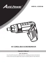
Page 1: ...4V CORDLESS SCREWDRIVER MODEL ACSD368...

Page 2: ...2 TABLE OF CONTENTS TABLE OF CONTENTS 2 IMPORTANT SAFETY INSTRUCTIONS 3 SPECIFICATIONS 4 FUNCTIONAL DESCRIPTION 4 OPERATION 5 MAINTENANCE 7 PARTS LIST 8 SCHEMATIC DRAWING 9...

Page 3: ...ildren if work is hazardous Keep tools away from children during and after work Make sure body position is steady as you work Remember that falls constitute an important source of accident Make sure y...

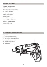
Page 4: ...sories 8pcs Sockets 1pc 1 Screw bit holder 1pc 2 3 8 Screw bit holder 28pcs 1 Screwdriver bits 6pcs HSS Drill bits 1 Chuck 2 Battery Capacity Indicator 3 Two Position Adjustment Button 4 Forward Rever...

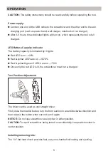
Page 5: ...LED is on 20 Red yellow LED s are on 20 70 Red yellow green 3 LED s are on 70 Once only the red LED is lit the screwdriver must be re charged Two Position Adjustment The driver can be used as one stra...

Page 6: ...to make sure it is secured in the chuck It s normal to have a small gap for bit installation NOTE Only use bits with quick connecting locking groove To remove bits Lock the trigger by placing the rota...

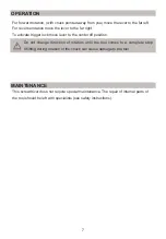
Page 7: ...lock move lever to the center off position Do not change direction of rotation until the tool comes to a complete stop Shifting during rotation of the chuck can cause damage to the tool This screwdri...

Page 8: ...ing 1 22 P_ 039_ 10A_ Adjusting ring_ rear 1 23 P_ 039__11A_ _Adjusting ring_ front 1 24 P__039_ A03A_ PCB batterybar 1 25 P_ 039_ 03A_ Housing main_ upside__left 1 26 P_ 039_ 12A_ Index spring 1 27 L...

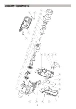
Page 9: ...9 SCHEMATIC DRAWING...

Page 10: ......

Reviews: