FC726 Guide
8
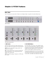
6. DIP Switches
These eight DIP switches (numbered 1–8 from left to right) set
various modes on the FC726. Switches 3–5 and 7 are not cur-
rently implemented.
Switch #1 Bidirectional mode
Flip this switch when converting between third-party formats
using one FC726.
Switch #2 MADI MERGE
When set to MADI MERGE (down), Format B MADI Input 1
channels 1–24 are merged with Format B MADI Input 2 chan-
nels 1–28 and Format B MADI Input 1 channels 25–28 to form
a single 56-channel input stream. Format B MADI Output 1
sends channels 1–56 and Format B MADI Output 2 sends
channels 25–56 followed by 1–24 from the third-party inputs.
Switch #6 AES MASTER/SLAVE
When set to SLAVE (up), the Format A AES outputs lock to
their corresponding AES inputs. Within each bank, all AES
outputs operate at the sample rate of the lowest-numbered,
locked AES input. For example, if the first bank (channels 1–8)
has a 44.1 kHz AES signal connected to inputs 1–2 and a 48
kHz input connected to inputs 5–6, then AES output channels
1–8 will all run at 44.1 kHz. If AES inputs are not present on a
bank, Format A will get sample clock from the Format B Sync
input. If sync is not present, Format A will then lock to the
Format B Sync Input.
When set to MASTER (down), Format A AES outputs get sam-
ple clock from the Format A Sync input. If Format A sync is
not present, the Format A AES outputs will then lock to the
Format B Sync Input.
Switch #8 AES STEREO/AES MONO
Set this switch to AES Stereo (up) for the normal configuration
where each AES signal contains two discreet channels. If the
sample rate is above 52 kHz (such as 88.2 or 96 kHz), and the
AES signal connected to the FC726 implements two-wire AES
(also referred to as mono mode AES), set the switch to AES
Mono (down). This setting treats each AES signal as a single
channel with a frame rate running at half its sample rate. For
example, a 96 kHz two-wire AES signal runs at 48 kHz by using
the left channel for the even samples and the right channel for
the odd samples. This switch affects both the AES inputs and
outputs.
7. Format A AES Sync In
Connect an AES sync signal to this XLR connector to synchro-
nize the Format A MADI signal. According to the AES specifi-
cation, the AES sync signal must use the same sample rate as
the incoming MADI signal to operate correctly.
8. SDIF-2 or SLAVE CLK IN
This connector can receive either an SDIF or slave clock sync
signal. The FC726 automatically detects which signal type has
been connected.
An SDIF device must send a word sync signal to this connector
to properly connect to the FC726.
9. SLAVE CLK OUT
If Slave Clk In has a valid sync signal, it is passed through to
Slave Clk Out. If Slave Clk In does not have a valid sync signal,
the lowest numbered bank that is locked and in use is selected
as the clock source.
It is possible, but not recommended, to connect a
MADI signal without using a corresponding sync
signal. Providing an AES or Word sync results in
lower jitter and should be used whenever possible.
Summary of Contents for FC726
Page 1: ...FC726 Guide System 5...
Page 4: ...FC726 Guide iv...
Page 8: ...FC726 Guide 4...
Page 14: ...FC726 Guide 10...
Page 18: ...FC726 Guide 14...
Page 34: ...FC726 Guide 30...
Page 35: ......


