background image

This document describes how to identify and replace a failed Avid ISIS Storage Blade (ISB) 
Controller Board in an Avid ISIS | 7500 or 7000. 

Use this procedure 

only

 to replace an ISB Controller board or to repair an ISB that has experienced a 

boot problem, due to a faulty Controller board. ISIS | 7500 and 7000 ISB boot issues can manifest in 
either of the following ways after a power down or power up event:

The ISB appears in the Storage Manager or Storage Element page with a Memory Error status

The ISB will not boot and the LED will remain lit solid amber

n

The “no connection” status does not always indicate a faulty Controller board. Verify the nature of the 
failure before replacing the board. 

Verifying an ISB Boot Failure Condition

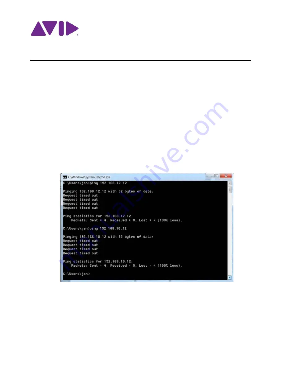
1. Verify that the ISB (IP address) does not respond over the network with the 

ping

 command on 

both VLANs.

2. Verify that the ISB LED is solid amber (on an i4000 or i8000) or alternating irregularly between 

amber and green (i1000 and i2000).

3. Check the ISB boot status using the switch Agent page, as follows:

a.

Open the switch Agent page.

b.

Click the Advanced tab.

c.

Select “Issue shell command” and type the following command in the text box:

ISIS

®

 7000 ISB Controller Board Replacement

Summary of Contents for ISIS 7000 ISB

Page 1: ...l not boot and the LED will remain lit solid amber n The no connection status does not always indicate a faulty Controller board Verify the nature of the failure before replacing the board Verifying a...

Page 2: ...nt ISB Controller Board replace the failed one Return the failed Controller board to Avid On the RMA sheet indicate ISB Controller Board boot problem Replace a failed ISB Controller board with the cor...

Page 3: ...ler Board from a spare ISB upgrade the firmware on the spare ISB before using this replacement procedure Using an ISB Controller Board with an incorrect firmware version could result in data loss Refe...

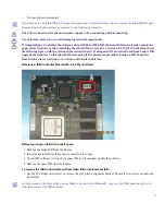
Page 4: ...ear drive from the enclosure Label this drive as rear drive n Be careful to hold the SATA connecting board in the middle to support it 3 Remove the remaining screws for the plastic slide and remove th...

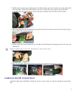
Page 5: ...d pull the front drive towards the front of the enclosure freeing that drive from the SATA connecting board 7 Gently pull the SATA connecting board out of the ISB Controller Board while keeping the si...

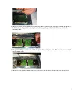
Page 6: ...ing tab facing away from you The connector is keyed to fit in the correct orientation 3 Install the SATA connecting board by carefully aligning the pins You can wiggle the SATA connecting board to ali...

Page 7: ...he connecting board while you gently push the drive SATA connector into the connecting board 7 Using the 2 Phillips screwdriver install the two plastic slides with eight screws Make sure the screws ar...

Page 8: ...hat it boots properly green LED 2 Verify that you can ping it on both IP addresses and you are able to access the ISB Web page for that particular ISB 3 Make sure the ISB shows a status of Rectifying...

Reviews: