Chapter 3: DADman Software
15
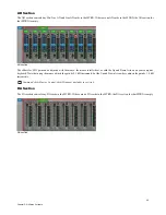
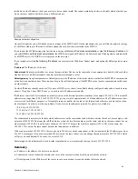
In the Detailed matrix view, a blue circle is displayed at the top of the column if an input channel is already routed to an output channel.
The circle is dark blue if an input channel that is shown in the current Detailed matrix (because the source is selected in the Overview
matrix) is already routed to the output channel. The circle is light blue if an input channel from another source, not shown in the current
Detailed matrix (because it is not selected in the Overview matrix) is already routed to the output.
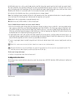
In the left side of the Detailed matrix, there is a status indicator for each input channel:
Green
On a digital input, green indicates that there is a valid input and carrier. It does not indicate whether there is an audio signal pres-
ent on the channel. For an analog channel, it indicates that the expansion card is present.
Yellow
Indicates lost synchronization or mismatched sample rates.
Red
Indicates an error with the interface, such as no input signal.
To route individual input channels to one or more output channels:
1
In the Overview matrix, click in the junction of an input source (Inputs are listed in the rows on the left)—such as an installed analog
input expansion card (AD) or one of the built-in digital input ports, like AES/EBU, or Pro Tools output channels (DigiLink)—and
the output destination you want (Outputs are listed in the columns on the top)—such as an installed analog output expansion card
(DA) or one of the built-in digital output ports, like MADI coax, or Pro Tools input channels (DigiLink). The junction turns blue and
the Detailed channel to channel routing matrix appears to the right.
2
In the Detailed matrix, click in the junction of the input channel for the selected source (each input channel is listed in the rows on
the left) and the output channel to which you want route the signal (each output channel is listed in the columns on top). A blue circle
indicates that the input channel (row) is routed to an output channel (columns).
3
To route a single input channel to multiple output channels, click in each column (outputs) in the same row (input) to make each con-
nection.
To disconnect an input and output:
Click any crosspoint connection (blue) to disconnect it.
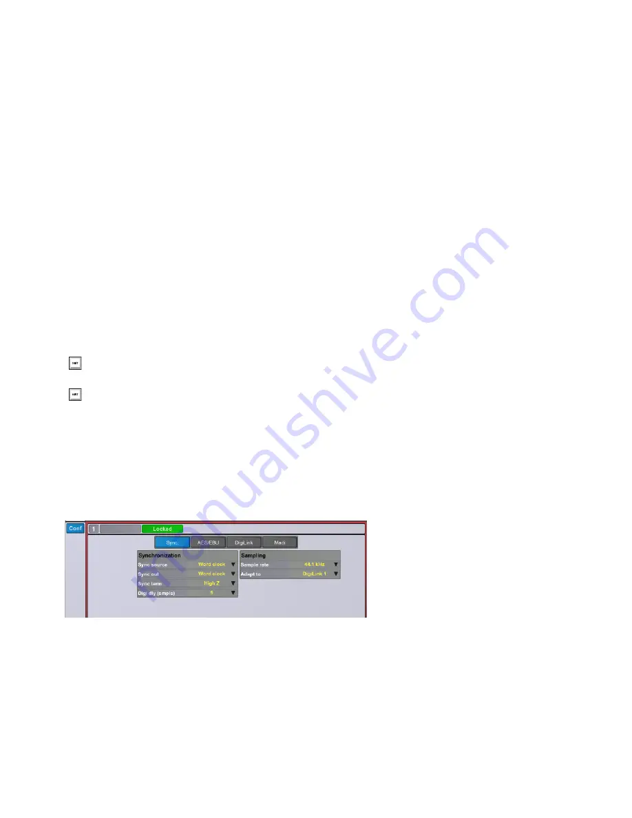
Configuration Section
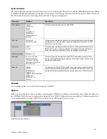
The Configuration section is divided into subsections, such as Synchronization, AES/EBU, DigiLink, MADI, and Optical 1 and Optical
2 (if present).
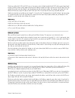
Shift-click to connect consecutive pairs of input channels to consecutive pairs of output channels.
Command-click (Mac) or Control-click (Windows) to connect all input channels in order to consecutive output channels in order. The
connection points are made diagonally from the top left down and to the right.
General section

