Chapter 6: Installing Modules
53
Installing Modules
Install all modules beginning with the left-most chassis. Begin with the slot/module closest to the front (slot 1). In our example
S6 M40 24-5 configuration we are installing channel modules in the left-most chassis, so the first (front-most) module to install is
a Fader Module. In other configurations the left-most chassis could be for Master modules (see “Installing Master Section Mod-
ules” on page 56).
Installing Channel Modules
To install Channel modules:
1
If you have not already done so, unpack one Fader Module.
2
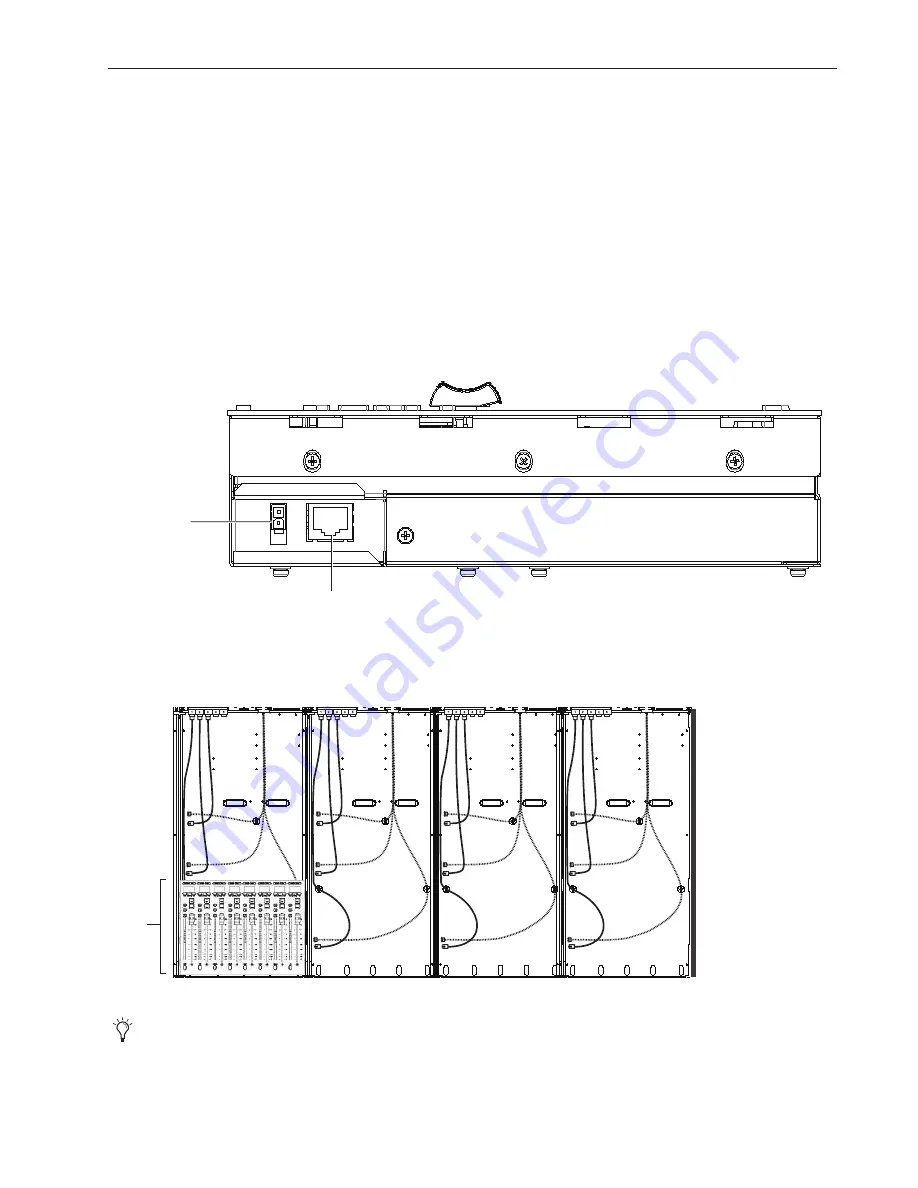
Holding the Fader Module close to its chassis, do the following:
• Connect the longest 2-pin Molex power cable among those in the built-in Cable Harness to the DC input on the side of the
module.
• Use one of the longest RJ-45 cables in the built-in Cable Harness and connect it to the Ethernet port on the side of the module.
3
Install the connected Fader Module into the slot 1 (the front-most slot) in the chassis, being careful to orient it correctly and seat
it at the front edge of the chassis. In our example we are installing the first Fader Module into slot 1 of the first (left-most) chas-
sis. Make sure the module sits completely into the frame and not on any cables.
Power and Ethernet ports on the Fader Module
Fader Module in slot 1 of the chassis (switch and PSUs not shown)
Later, after all modules are in place, they will be secured within their chassis by installing Compression Panels and T-Strips.
Gigabit Ethernet RJ-45
Power
Slot 1
Fader
Module
Summary of Contents for Pro Tools S6 Master Post Module
Page 1: ...Avid S6 Installation Guide ...
Page 4: ......
Page 7: ...Part I Introduction ...
Page 8: ......
Page 19: ...Part II Frames ...
Page 20: ......
Page 39: ...Part III Modules ...
Page 40: ......
Page 58: ...Avid S6 Installation Guide 50 ...
Page 74: ...Avid S6 Installation Guide 66 ...
Page 80: ...Avid S6 Installation Guide 72 ...
Page 81: ...Part IV Appendices ...
Page 82: ......
Page 91: ......


