background image

Avidyne 700-00182-XXX and 700-00179-XXX 

 Instructions for Continued Airworthiness 

Confidential property of Avidyne Corporation 


AVIFD-315 

Not to be disclosed without permission 


Revision: 08, Date: 01/18/17 


Page 2 of 2 


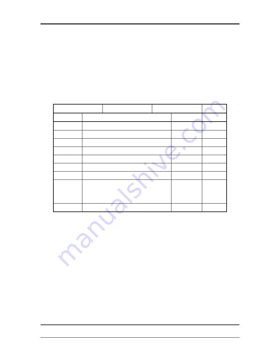
Document Revision History 


Document Number 

AVIFD-315 

Control Category


Revision 

Description 

ECO 

Date 

00


Initial Release


ECO-13-199


08/30/13


01 

AEG Comments 

ECO-13-350  09/27/13 

02 

Update Part Numbers 

ECO-13-405  01/20/14 

03 

Removing ADS-B 

ECO-14-059  03/03/14 

04 

Added 700-00179-XXX 

ECO-15-129  03/20/15 

05 

AEG Comments 

ECO-15-169  04/22/15 

06 

FAA Comments 

ECO-15-193  05/05/15 

07 

Update f or Release 10.2. Added 
IFD410, IFD510, IFD545, IFD550, ARS 
troubleshooting instructions and IFD550 
figure 

ECO-16-326  12/21/16 

08 

Address AEG comments sections 2, 6, 7 

ECO-17-013  01/18/17 

Summary of Contents for 700-00179 Series

Page 1: ...x Green Suite 221 561 Virginia Road Concord MA 01742 Avidyne 700 00182 XXX and 700 00179 XXX Integrated Flight Display Instructions for Continued Airworthiness Important Notice With respect to the AML STC the physical mounting of antennas are specifically excluded from the approval in the case of installations on the pressure vessel of pressurized aircraft or composite aircraft unless approved dat...

Page 2: ...sion Description ECO Date 00 Initial Release ECO 13 199 08 30 13 01 AEG Comments ECO 13 350 09 27 13 02 Update Part Numbers ECO 13 405 01 20 14 03 Removing ADS B ECO 14 059 03 03 14 04 Added 700 00179 XXX ECO 15 129 03 20 15 05 AEG Comments ECO 15 169 04 22 15 06 FAA Comments ECO 15 193 05 05 15 07 Update f or Release 10 2 Added IFD410 IFD510 IFD545 IFD550 ARS troubleshooting instructions and IFD5...

Page 3: ...ent Locations 9 3 Control and Operation Information 11 3 1 Page Function Keys 12 3 2 Line Select Keys 12 4 Servicing Information 12 5 Maintenance Instructions 13 5 1 Scheduled Maintenance 13 5 2 Recommended periodic scheduled servicing tasks 13 5 3 Software Upgrade 14 6 Troubleshooting Information 15 7 Removal and Replacement Information 17 7 1 IFD5XX IFD4XX Removal 17 7 2 IFD5XX IFD4XX Installati...

Page 4: ...1 18 17 Page 4 of 4 11 For Commuter Category Aircraft 19 12 Recommended Overhaul Periods 19 13 Airworthiness Limitations Section 19 14 Revision 20 15 Assistance 20 16 Implementation and Record Keeping 20 List of Figures Figure 1 IFD5XX IFD4XX Location Single Engine 9 Figure 2 IFD5XX IFD4XX Location Multi Engine 10 Figure 3 IFD540 510 Unit 11 Figure 4 IFD4XX Unit 11 Figure 5 IFD545 550 Unit 11 ...

Page 5: ... Aircraft Maintenance Manual and the operator s Aircraft Scheduled Maintenance Program 1 1 Applicability This document applies to aircraft altered by the installation of the following equipment Equipment should be installed using data listed in 700 00182 XXX 700 00179 XXX Integrated Flight Display Master Document List document number AVIFD 306 Table 1 IFD Part Number Variants Part Number Descripti...

Page 6: ...RATED FLIGHT DISPLAY IFD545 BLACK BEZEL WITH VIDEO 700 00182 130 INTEGRATED FLIGHT DISPLAY IFD545 GREY BEZEL 700 00182 131 INTEGRATED FLIGHT DISPLAY IFD545 GREY BEZEL WITH VIDEO 700 00182 020 INTEGRATED FLIGHT DISPLAY IFD550 BLACK BEZEL 700 00182 021 INTEGRATED FLIGHT DISPLAY IFD550 BLACK BEZEL WITH VIDEO 700 00182 120 INTEGRATED FLIGHT DISPLAY IFD545 GREY BEZEL 700 00182 121 INTEGRATED FLIGHT DIS...

Page 7: ... IFD440 Pilot s Guide 600 00317 000 IFD550 and IFD545 Pilot s Guide 600 00318 000 IFD510 Pilot s Guide 600 00319 000 IFD410 Pilot s Guide 1 6 Distribution This Instruction for Continued Airworthiness is to be furnished with new production IFD systems and is to become part of the permanent aircraft records upon installation A current revision of this ICA shall be available on the Avidyne website at...

Page 8: ...0 Same as IFD540 but with integral attitude reference sensor ARS add l page button SVS IFD545 Same as IFD540 but with integral attitude reference sensor ARS add l page button SVS without NAV COM functions GPS only left knob removed IFD510 Same as IFD540 but without NAV COM functions GPS only left knob removed IFD440 Baseline 4 8 Display unit with GPS NAV COM IFD410 Same as IFD440 but without NAV C...

Page 9: ...ion 08 Date 01 18 17 Page 9 of 9 2 1 Equipment Locations The installer should indicate on the outlines below the locations for the following items at the time of installation IFD5XX IFD4XX unit wire harness location and routing coaxial cables and antennas Use Figure 1 for single engine airplanes or Figure 2 for multi engine airplanes Figure 1 IFD5XX IFD4XX Location Single Engine ...

Page 10: ... 00179 XXX Instructions for Continued Airworthiness Confidential property of Avidyne Corporation AVIFD 315 Not to be disclosed without permission Revision 08 Date 01 18 17 Page 10 of 10 Figure 2 IFD5XX IFD4XX Location Multi Engine ...

Page 11: ...sed without permission Revision 08 Date 01 18 17 Page 11 of 11 3 Control and Operation Information The IFD5XX IFD4XX System can be controlled using the button and knobs on the bezel of the unit Alternately some functions can be controlled using the touch screen on the unit s display Figure 3 IFD540 510 Unit Figure 4 IFD4XX Unit Figure 5 IFD545 550 Unit ...

Page 12: ...ker nature to it Select the page of interest by pressing the middle of the Page Function Key and navigate through the available tabs by pressing the left or right 3 2 Line Select Keys Line Select Keys typically abbreviated to LSK are the buttons found along the left side of the bezel A label just inside the bezel adjacent to the physical LSK indicates the function of the LSK Pressing the LSK or th...

Page 13: ...rworthy condition and function 1 During any maintenance activities involving the IFD System perform i e IFD removal cable repair a post installation check as described in Installation Manual Integrated Flight Display Installation Manual 600 00299 000 2 Visually inspect no magnification required wire bundle coaxial cables overbraid if installed and routing for evidence of damage chafing grounding s...

Page 14: ...procedure instructions 3 It is the responsibility of maintenance personnel to ensure the identified part is recorded in the necessary maintenance logs 4 It is the maintenance personnel s responsibility to ensure that the software part identification has been logged When new software is loaded into the unit the correct software part number should be verified according to the instructions accompanyi...

Page 15: ...ery low Antenna Verify the GPS antenna is connected to the correct antenna Repair or Replace antenna Antenna shaded from satellites Move aircraft to a better location Interference from avionics Re route GPS antenna system away from sources of interference Interference from a VHF Communication transmitter Move GPS antenna away from the VHF Communication antenna or install a 1575 22 MHz notch filter...

Page 16: ...X IFD4XX to the correct station ARINC device ARINC 429 is not receiving transmitting data from the IFD5XX IFD4XX Wiring Make sure wire harness is connected Check the wire harness and repair or replace if needed IFD5XX IFD4XX configuration Verify the IFD5XX IFD4XX is configured for the ARINC device Verify the ARINC 429 device speed is set correctly on the IFD5XX IFD4XX RS 232 device ARINC 429 is no...

Page 17: ...engage the electrical connectors 3 Remove unit from tray 7 2 IFD5XX IFD4XX Installation 1 Slide the IFD5XX IFD4XX unit into the tray 2 Insert a 3 32 hex wrench into the hole on the front panel on the IFD5XX IFD4XX and engage locking screw 3 Turn the locking screw clockwise to tighten the locking cam until the unit is flush to the tray 4 Perform post installation verification per Section 7 7 7 3 GP...

Page 18: ...performed Verify the following functions of the IFD5XX IFD4XX is operating correctly reference the IFD5XX IFD4XX Installation Manual and Pilot Guide as need The installation manual Avidyne Document 600 00299 000 Rev 10 or later FAA approved revision contains detail setup and testing information if needed 7 7 1 VHF Communication Checkout Tune the VHF Communication Transceiver to an unused frequency...

Page 19: ... 000 Rev 10 or later FAA approved revision contains the wiring diagrams for the system Also reference FAA AC 43 13 as needed 10 List of Special Tools No special tools are required for this installation 11 For Commuter Category Aircraft This section is not applicable 12 Recommended Overhaul Periods No overhaul periods are required for this installation 13 Airworthiness Limitations Section There are...

Page 20: ...e revisions to this manual please furnish the information listed below Name Address City State and ZIP Code Part Number of Manual Current Revision Status of the Manual E mail address Phone Number Please submit this information to Avidyne Corporation 4 Middlesex Green Suite 221 561 Virginia Road Concord MA 01742 15 Assistance For questions or assistance regarding this ICA contact Avidyne Corporatio...

Reviews: