Radar Page (Optional)
Avidyne EX500/EX600 MFD
-38-
600-00078-001 Rev 05
4.3
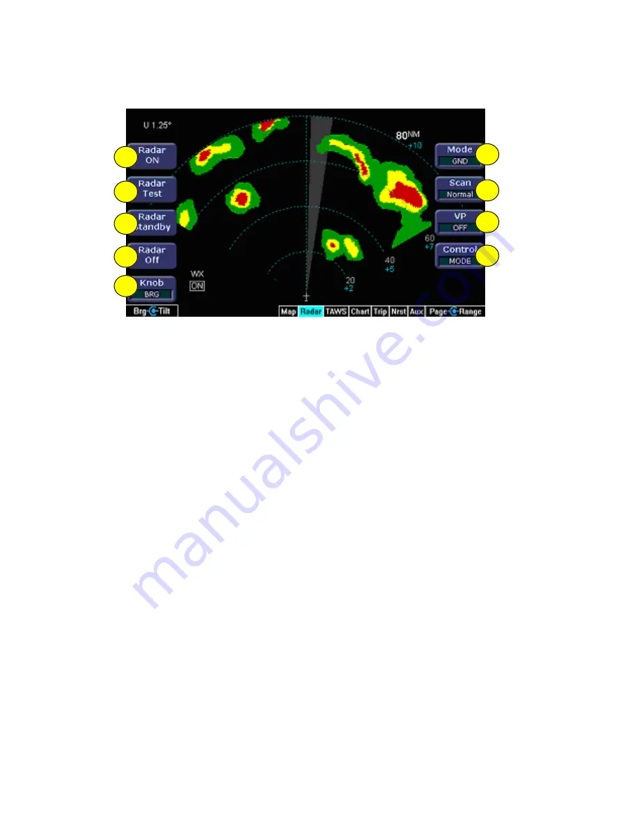
Dedicated Radar in Ground Mode
Figure 4.3 Dedicated Radar Page in Ground Mode
1) Radar ON
- Turns the radar on in normal operation. If the radar is
on, the mode annunciator is set to ON, and the moving scan
indicator, radar echoes are visible.
2) Radar Test
- Initiates a radar self-test function that is monitored
by the EX500/EX600. The test function is confirmed by the
presence of the test annunciation and the test pattern display.
During self test, all of the circuitry and functions of the R/T are
exercised with the exception of the magnetron tube. No
microwave energy is emitted in the test function. The display will
have a test pattern with the following colors: green, yellow, red
and magenta.
3) Radar Standby
- Places the radar circuitry in an energized but
inactive state. Select Standby as soon as it is practical to do so
after starting the EX500/EX600. When the radar is in standby, the
mode annunciator is set to STBY, and the moving scan indicator
and radar echo returns are not present. Standby mode also
places the antenna in the desired park position.
4) Radar Off
- Removes power from the radar. The antenna does
not scan and no microwave energy is emitted. When the radar is
off, the mode annunciator is set to OFF, and the moving scan
indicator and radar echo returns are not present.
9
8
7
5
4
3
2
1
6
Summary of Contents for FlightMax EX500
Page 1: ...600 00078 001 Rev 05 Multi Function Display Pilot s Guide Software Release 4 or Later ...
Page 2: ......
Page 38: ...Map Page Avidyne EX500 EX600 MFD 26 600 00078 001 Rev 05 THIS PAGE INTENTIONALLY LEFT BLANK ...
Page 90: ...Trip Page Avidyne EX500 EX600 MFD 78 600 00078 001 Rev 05 THIS PAGE INTENTIONALLY LEFT BLANK ...
Page 183: ......


