IFD400 Series Pilot Guide
2-2
FMS Subsystem
FPL (FLIGHT PLAN) TAB
FMS BASIC CONCEPTS
NOTE
FMS-Centric Calculations
The FMS presumes the pilot intends to fly the flight
plan as created. All deviation data, most datablock
data, and the times to go and fuel calculations are all
based on that assumption.
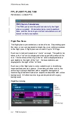
Flight Plan Rows
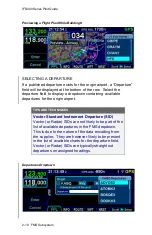
The flight plan is presented as a series of rows. Depending upon
the view, a row can represent a single leg or an entire procedure
in the flight plan. A flight plan can consist of up to 128 legs.
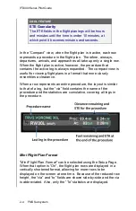
Each row is laid out based on a “via-to” concept. The path to be
taken is the “via” and is displayed in the upper left portion of the
row. The terminus of the leg is the “to” and is displayed below
and s
lightly to the right of the “via”. Various statistics are
displayed to the right of the “to” field.
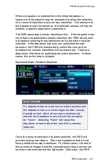
Each row in the flight plan is color-coded to aid in identifying
important features at a glance. Overriding all other colors, the
active leg is always depicted with a magenta background.
Inactive legs that terminate at an airport are depicted with a blue
background. All other inactive legs are depicted with a gray
background.
Flight Plan Coloring
Summary of Contents for IFD410 FMS/GPS
Page 1: ......
Page 8: ......
Page 56: ......
Page 100: ...IFD400 Series Pilot Guide 2 44 FMS Subsystem Info Tab Nearby Navaids ...
Page 160: ......
Page 250: ...IFD400 Series Pilot Guide 4 90 Aux Subsystem ADS B Unavailable Products Page ...
Page 252: ......
Page 378: ......


