IFD500 Series Pilot Guide
FMS Subsystem 3-31
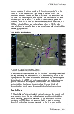
increments and the inner knob for 0.1 nm increments. Turn the
knob left for left offsets and right for right offsets. Once the
intended offset has been entered, press th
e “Confirm Right/Left
x.x NM” LSK. At that point, the original LSK will indicate “Offset
Route Right/Left X.X NM”. To delete a lateral offset, press the
“Delete Offset” LSK. The maximum offset that can be dialed in is
20 NM. Lateral offsets are not available when in OBS mode.
Lateral offsets are unaffected by graphical route planning (“rubber
banding”) operations.
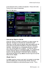
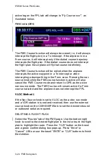
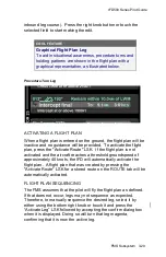
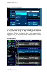
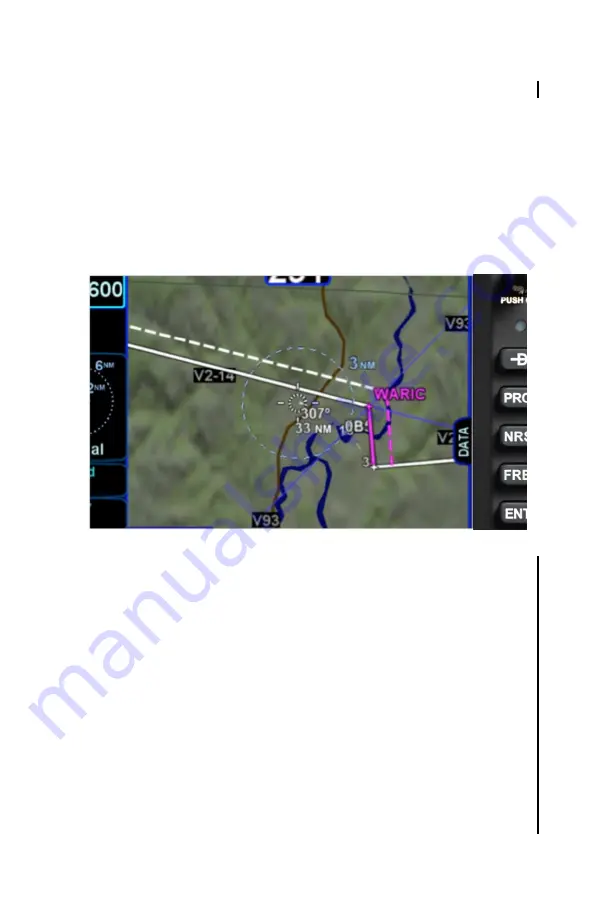
Lateral Offset Map Depiction
FLIGHT PLAN DISCONTINUITIES
A discontinuity indicates that the FMS cannot provide guidance to
the leg following the discontinuity. If a discontinuity exists in the
flight plan and the FMS reaches the end of the leg preceding the
discontinuity, the FMS will not sequence the leg and will provide
guidance outbound along the same course until some overt
action is taken to change the active leg. Several kinds of
discontinuities exist, each discussed in the following sections.
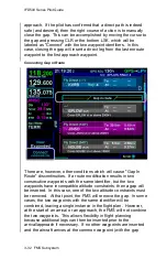
Gap In Route
A "Gap In Route" discontinuity is typically caused by the entry of
an approach when the preceding leg does not terminate at the
same waypoint as the first waypoint in the approach. This is
because the FMS does not assume that it is safe to proceed
directly from the last enroute waypoint to the first point on the
Summary of Contents for IFD510
Page 1: ......
Page 140: ...IFD500 Series Pilot Guide 3 50 FMS Subsystem Weather Data on Info Tab Info Tab Nearby Navaids ...
Page 150: ...IFD500 Series Pilot Guide 3 60 FMS Subsystem User Waypoint Airfield Naming Example ...
Page 156: ......
Page 180: ...IFD500 Series Pilot Guide 4 24 Map Subsystem ADS B Lightning Coverage Area Shadow ...
Page 252: ...IFD500 Series Pilot Guide 5 16 Aux Subsystem Trip Statistics Calculator ...
Page 460: ...IFD500 Series Pilot Guide 7 82 General Bluetooth pairing pairing code ...


