IFD500 Series Pilot Guide
Map Subsystem 4-15
can easily be seen if the IFD were on the FPL tab of the FMS page
and using the split Map-FPL view.
TIPS AND TECHNIQUES
Optimal Rubber Banding
If you don’t see the desired leg turn cyan within 2
seconds of placement of your finger on the location, try
slightly adjusting the placement of the finger that is
being used to designate a leg for rubber banding. Move
your finger slightly in a direction perpendicular to the
leg. Note that any leg can be rubber-banded including
the active leg (the magenta one) unless the leg is part of
a published instrument procedure.
Rubber banding is a handy feature to quickly alter a flight plan
around airspace or a weather buildup while staying on the map.
NOTE
Rubber Banding Only Via Touch
Rubber banding can only be accomplished via touch
screen controls. There is no physical bezel control to
support the feature.
NOTE
Rubber Banding Not Functional in SVS View
Rubber banding is not supported in the exocentric
synthetic vision view of the flight plan on the SVS tab of
the MAP page.
Summary of Contents for IFD510
Page 1: ......
Page 140: ...IFD500 Series Pilot Guide 3 50 FMS Subsystem Weather Data on Info Tab Info Tab Nearby Navaids ...
Page 150: ...IFD500 Series Pilot Guide 3 60 FMS Subsystem User Waypoint Airfield Naming Example ...
Page 156: ......
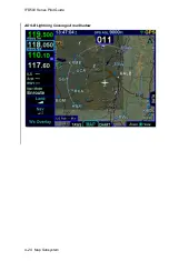
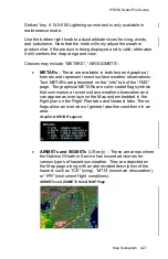
Page 180: ...IFD500 Series Pilot Guide 4 24 Map Subsystem ADS B Lightning Coverage Area Shadow ...
Page 252: ...IFD500 Series Pilot Guide 5 16 Aux Subsystem Trip Statistics Calculator ...
Page 460: ...IFD500 Series Pilot Guide 7 82 General Bluetooth pairing pairing code ...

