IFD500 Series Pilot Guide
4-74 Map Subsystem
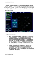
The radar mode is controlled by a line select key along the left side
labeled “Radar”. Pressing the LSK or touching the label will generate
a drop down list of the available modes. Turn the bottom right knob to
scroll through the list or touch the desired mode in the list to select it.
Radar Mode Control
The possible modes are:
Test
– when selected, initiates a radar self-test function that
is monitored by the IFD. The test function is confirmed by
the presence of the test annunciation and test pattern
display. During self-test, all of the circuitry and functions of
the R/T are exercised with the exception of the magnetron
tube. No microwave energy is emitted in the test function.
The display will have a test pattern with the following colors:
green, yellow, red, and magenta.
Standby
– the system will always power up in this mode.
Standby places the radar circuitry in an energized but
inactive state. In Standby, the moving scan indicator and
radar echo returns are not present and the antenna is placed
in the desired park position.
Summary of Contents for IFD510
Page 1: ......
Page 140: ...IFD500 Series Pilot Guide 3 50 FMS Subsystem Weather Data on Info Tab Info Tab Nearby Navaids ...
Page 150: ...IFD500 Series Pilot Guide 3 60 FMS Subsystem User Waypoint Airfield Naming Example ...
Page 156: ......
Page 180: ...IFD500 Series Pilot Guide 4 24 Map Subsystem ADS B Lightning Coverage Area Shadow ...
Page 252: ...IFD500 Series Pilot Guide 5 16 Aux Subsystem Trip Statistics Calculator ...
Page 460: ...IFD500 Series Pilot Guide 7 82 General Bluetooth pairing pairing code ...

